


14 Drain Line
Rev A
Drain Line
Drain Line Connection
1. The unit should be above and not more than 20 feet (6.1 m) from the
drain. Use an appropriate adapter fitting to connect 1/2-inch (1.3 cm)
plastic tubing to the drain line connection of the control valve.
2. If the backwash flow rate exceeds 5 gpm (22.7 Lpm) or if the unit is
located 20-40 feet (6.1-12.2 m) from drain, use 3/4-inch (1.9 cm)
tubing. Use appropriate fittings to connect the 3/4-inch tubing to the
3/4-inch NPT drain connection on valve.
3. The drain line may be elevated up to 6 feet (1.8 m) providing the run
does not exceed 15 feet (4.6 m) and water pressure at the conditioner
is not less than 40 psi (2.76 bar). Elevation can increase by 2 feet (61
cm) for each additional 10 psi (.69 bar) of water pressure at the drain
connector.
4. Where the drain line is elevated but empties into a drain below the
level of the control valve, form a 7-inch (18-cm) loop at the far end of
the line so that the bottom of the loop is level with the drain line
connection. This will provide an adequate siphon trap.
Where the drain empties into an overhead sewer line, a sink-type trap
must be used.
Secure the end of the drain line to prevent it from moving.
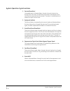
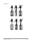
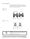
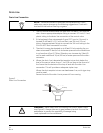
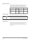
Figure 3
Drain Line Connection
NOTE: Standard commercial practices are expressed here. Local
codes may require changes to the following suggestions. Check with
local authorities before installing a system.
Right Way
Air Gap
Drain
WARNING: Never insert drain line directly into a drain, sewer line or
trap (Figure 3). Always allow an air gap between the drain line and the
wastewater to prevent the possibility of sewage being
back-siphoned into the conditioner.