


10
IMPORTANT: ENSURE THAT THE APPLIANCE IS
CORRECTLY ADJUSTED FOR THE GAS TYPE AND
CATEGORY APPLICABLE IN THE COUNTRY OF
USE. REFER TO DATABADGE AND TECHNICAL
SPECIFICATIONS OF THIS BOOKLET. FOR
DETAILS OF CHANGING BETWEEN GAS TYPES
REFER TO SECTION 11, REPLACING PARTS.
1. CONTROL UPGRADE
1.1 This stove is fitted with a control valve that can be easily
upgraded to battery powered remote control. There are two
versions of this control which can be obtained through your
local Gazco stockist.
1.2 This upgrade can be fitted before or after installation but if
side clearances are limited then it will be easier to upgrade
the stove before installation. Full instructions are included
with the kit.
1.3 STANDARD REMOTE CONTROL
This remote control can control the gas appliance after the
pilot has been lit. It can turn the main burner on and
regulate it from low through to high and back again. It can
turn the main burner off leaving the pilot burning. GAZCO
PART NUMBER 8455.
1.4 THERMOSTATIC AND TIMER REMOTE CONTROL
This remote control can control the gas appliance after the
pilot has been lit. In "MANUAL MODE" it can be used to
turn the main burner on and manually regulate it from low
through to high and back again. It can also be used to turn
the main burner off leaving the pilot burning. In "AUTO
MODE" it will automatically regulate the room temperature.
In "TIMER MODE" it will turn the fire on and off according
to a pre-set programme and automatically regulate the room
temperature during two on periods. GAZCO PART NUMBER
8456.
2. SAFETY PRECAUTIONS
2.1 This appliance must be installed in accordance with the rules
in force, and used only in a sufficiently ventilated space.
Place read these instructions before installation and use of
this appliance.
2.2 All the instructions must be left intact with the user.
2.3 In your own interests and those of safety, this appliance must
be installed by a competent person in accordance
with local and national codes of practice. Failure to install
the appliance correctly could lead to prosecution.
2.4 This appliance is intended for use on a governed gas
installation and set to the required pressure.
2.5 Keep all plastic bags away from young children.
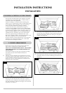
2.6 Do not place any object on or near to the stove. Allow
adequate clearance above the stove. See diagram 2 Site
Requirements, Appliance Location.
2.7 The stove is fitted with the Gazco Flue Sure System, which
will act to cut off the gas supply to the appliance in the
event of incorrect operation of the flue. If the system acts to
shut off the gas supply, this indicates that there is insufficient
flue pull. If this occurs a minimum of 10 minutes should be
allowed before trying to relight. Continued operation of this
safety device means that there may be a serious problem
with the flue system; a qualified gas engineer should inspect
this. DO NOT USE THE STOVE UNTIL AN ENGINEER SAYS
IT IS SAFE TO DO SO.
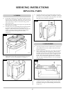
2.8 The Flue Sure System must not be tampered with. Use only
genuine Gazco replacement parts when servicing the system
- refer to Servicing section, Replacing Parts.
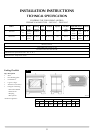
3. INSTALLATION OF THE STOVE
FLUE PIPE INSTALLATION
3.1 Open the carton and remove accessory carton and stove
unit. It will now be necessary to decide upon top or rear flue
exit, the stove is factory built for rear flue exit, but it may be
changed to top exit by using the following method.
3.1.1 Remove the flue spigot from the rear of the stove and
replace with the blanking plate from the top of the stove and
vice versa.
3.2 When installing with a top flue, please note the flue pipe fits
through a hole in the top grill, the dimensions are for floor
fixing a top flue installation with clearance for side panels.
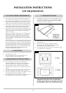
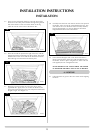
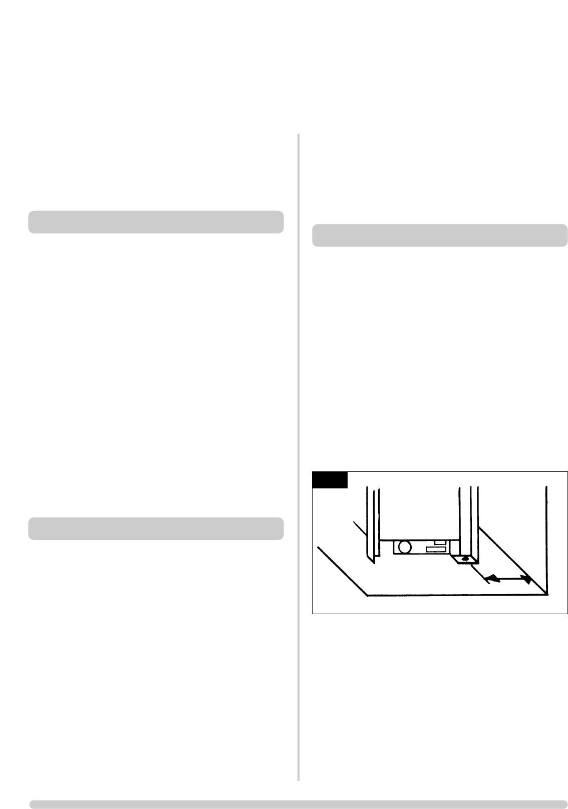
3.3 Position the engine assembly in its intended location and
mark the position of the floor fixing holes at the base of each
side of the subframe, minimum fixing dimensions to a rear
wall are showin in Diagram 3
3.4 Remove the assembly and drill the two holes using a No.12
masonry bit. Push the rawl plugs into the holes and place
the engine assembly in position. Secure to the floor using the
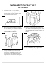
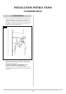
screws provided. Sea Diagram 1.
INSTALLATION INSTRUCTIONS
INSTALLATION
1
AR0631
158 mm