


9
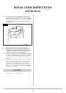
INSTALLATION INSTRUCTIONS
SITE REQUIREMENTS
1.1 The chimney or flue system must comply with the rules in
force, and must be a minimum of 127mm in diameter. (5").
1.2 The minimum height of the flue or chimney must be 3 metres
(10ft). Any horizontal flue run from the rear outlet should not
exceed 100mm from the back of the appliance.
1.3 The chimney or flue must be free from any obstruction. Any
damper plates should be removed or secured in the fully open
position and no restrictor plates should be fitted.
1.4 The chimney should be swept prior to the installation of the
appliance, but where it can be seen that the chimney is clean
and unobstructed throughout its entire length, it need not be
swept.
NOTE: If it is intended to fit the stove into an existing brick-
built chimney, a 5" (127mm) liner must be used. Larger
lined flues may work, but in some instances could cause
cold start flue problems resulting in nuisance shutdown.
Lined flues above 7" (175mm) are not recommended.
Due to recent changes to European chimney standards, new
flues and chimneys are now described by their temperature,
pressure and resistance to corrosion, condensation and fire. To
assist in identifying the correct flue system, the minimum flue
specification is shown in the Technical Specification in this
manual. Existing chimneys are not covered by this system.
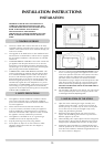
2.1 The large stove has a rated output in excess of 7Kw and
requires a minimum of 11cm
2
permanent effective free air.
This is in addition to any window that opens, and although
it must communicate with the outside air whenver possible,
it can communicate with an adjacent room providing such
space has a similar opening to the outside. The small and
medium stoves have a rated output below 7Kw and do not
normally require any additional ventilation.
3.1 Before installation, ensure the local distribution conditions
(identification of the type of gas and pressure) and the
adjustment of the appliance are compatible.
3.2 Ensure that the gas supply is capable of delivering the
required amount of gas, and is in accordance with the rules
in force.
3.3 Soft copper tubing and soft soldered joints can be used but
must not be closer than 50mm to the base of the tray.
3.4 A means of isolating the gas supply to the appliance must
be provided, independent of any appliance control.
3.5 All supply gas pipes must be purged of any debris that may
have entered, prior to connection to the appliance.
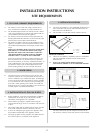
4.1 This stove must stand on a non-combustible hearth that is at
least 12mm thick and projects 50mm minimum from the
base of the fire in all directions.
4.2 Do not install in a room that contains a bath or shower.
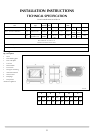
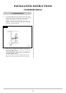
MINIMUM CLEARANCE
4.3 The fire is not suitable for installation against a combustible
wall. All combustible materials must be removed from
behind the fire.
4.4 Ensure you comply with all minimum clearance
measurements, whether or not to combustible materials.
The above dimensions provide adequate clearance at the
side and rear of the fire so that the controls can be reached.
3. INSTALLATION OF THE GAS SUPPLY
2. VENTILATION
4. APPLIANCE LOCATION
2
2A
1
A = 811mm
B = 527mm
C = 12mm
1. FLUE AND CHIMNEY REQUIREMENTS
AR0604
AR0531