


20
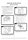
6.5 Disconnect the ignition lead from the gas valve.
6.6 Undo the two bolts securing the gas valve to the appliance
and remove the valve.
6.7 Replace in reverse order.
6.8 Check all joints for gas leaks. Check operation of the
thermocouple and ignition lead.
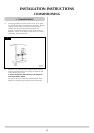
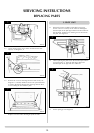
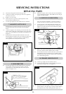
7.1 Turn the gas supply off at the isolation device. Undo the
thermocouple connection from the back of the gas valve.
Pull the sensor leads clear and remove the interrupter
block.
7.2 Undo the magnetic valve-retaining nut from the back of the
control valve. Gently tap out the magnetic valve and replace
with a new unit. Replace the retaining nut and tighten. See
diagram 12.
7.3 Reassemble the interrupter block and leads. Secure the
thermocouple connection in the rear of the gas control. (Do
not overtighten). Turn the gas supply on and check the
entire pipework and valve joints for any leaks.
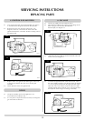
8.1 Turn the gas supply off at the isolation device. Locate the
main injector on the LH side of the airbox, undo the
compression nut and pull the pipe clear of the injector
body, see diagram 13, A.
8.2 Rotate the injector until it is fully removed, and install the
correct replacement injector. Reassemble and turn the gas
supply on, check for leaks.
.
If the stove has been installed in a restrictive location, it
may be necessary to remove the stove from its location.
9.1 Locate the sensor in the draught diverter opening, and
gently pull the two wires off the terminals. Undo the two
taptite screws and remove the sensor and the two plastic
spacers. See diagram 14.
9.2 Refit a new sensor ensuring the spacers are located between
the sensor and the bracket. Replace the two leads.
9.3 If it has been necessary to remove the stove, ensure that all
disturbed gas joints are checked for gas soundness when
reinstalled, and repeat the flue clearance test as detailed in
the Commissioning Section.
10.1 Turn the gas supply off at the isolation device.
10.2 Locate the aeration plate on the underside of the airbox
and remove the Nyloc nut, see diagram 15.
10.3 Remove the plate and replace with the correct size, ensure
that the hole(s) in the plate align correctly with the holes in
the underside of the airbox and replace the Nyloc nut.
SERVICING INSTRUCTIONS
REPLACING PARTS
8. MAIN INJECTOR
13
14
15
10. PRIMARY AERATION PLATE
AR0389
AR0381
A
7. MAGNETIC SAFETY VALVE
12
9. GAZCO FLUE SURE SYSTEM