


Form #43343330
–52– May 08
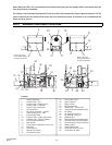
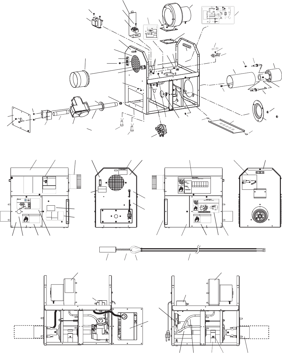
38a
22a
38
31
1
44
5
21
3
45
3
20
2
35
36
30
29
3
5, 5a
7
26
26a
25
24
1
22c
22b
14
1a
1a
22a
15
18
6
46
41, 41a
40
27
43
40a
3
17a
7
9a
Draft Inducer
Motor
Gas Valve
Air Switch
Transformer
Primary 120V
Secondary 24V
High Voltage Cable
Electrode
Gap 1/8
CONTINUE TO
ADDITIONAL
HEATERS
Terminal Block
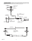
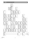
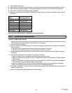
CONNECTION WIRING DIAGRAM
If any of the original wire as supplied with the
appliance must be replaced. It must be
replaced with wiring material having a
temperature rating of at least 105
o
C. (18
AWG. - UL / CSA 600V Type TEW)
When connecting the supply circuit to the
heater, wiring material having a minimum size
of 14 AWG and a temperature rating of at
least 90
o
C shall be used.
Schéma de circuit de connexion
Vers les autres
radiateurs
Plaque à
bornes
Transformateur
bobine primaire 120ÊV
bobine secondaire 24ÊV
pressostat
Robinet à gaz
Écartement
d'électrode
3,2Êmm
Haute tension
Bloc d'allumage
Moteur
d'amorce
d'aspiration
GND
V2
V1
(W)TH
Ignition Module (Fenwal)
(R) 24VAC
L1
IND
NC
P.SW
HV
S1
Flame Sensor
FACTORY WIRING
FIELD WIRING
Circuit d'origine
Connexions client
L2 NEUTRAL
L1 (hot) 120V
THERMOSTAT
(line voltage)
GROUND
MONITORING LIGHTS
Lampes témoins
42874020 6/07
Red
Light
Amber
Light
L1 Black
L2 Black
(ribbed)
Black
White
Black
(ribbed)
Black
Green
Green
Violet
Red
Blue
Green
Violet
Black
Yellow
Red
Orange
Orange
Fuse 2A
Fusible
Optional Low
Voltage (24V)
Thermostat
Remove jumper wire.
Blue
Blue
(jumper)
Terminal
Block
TISS
(Tube Integrity
Safety Switch)
Remove jumper wire.
Blue
Blue
(jumper)
Terminal Block
Plaque à
bornes
Blue
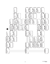
SCHEMATIC WIRING DIAGRAM
42785020 03/08
120V
GND
V2
V1
(W)TH
24VAC
L1
IND
NC
P.SW
HV
S1
MV MV
Motor
Transformer
24V
Igniter
Flame
Sensor
Ignition Module
Air
Switch
Thermostat
TISS
Red
Light
Gas
Valve
Amber
Light
7
23
3
22
52
61
16 17
1818
19
15
23
23
3332
48, 48a
48
47
12 8, 28 13
9
118, 11a
10 22a
34
31
38a
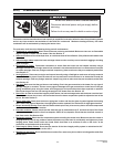
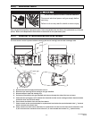
WARNING: Improper
installation, adjustment,
alteration, service or
maintenance can cause
property damage, injury
or death. Read the
Installation, Operating
and Maintenance
Instruction thoroughly
before servicing this
equipment.
AVERTISSEMENT: Une
installation, un réglage, une
modification, une réparation
ou un entretien incorrect peut
entraîner des dommages
matérials, des blessures ou
la mort. Lisez attentivement
les instructions dinstallation,
de fonctionnement et
dentretien avant de procéder
à linstallation ou à lentretien
de cet équipment.
WARNING: If not
installed, operated and
maintained in accordance
with the manufacturers
instructions, this product
could expose you to
substances in fuel or from
fuel combustion which can
cause death or serious
illness and which are
known to the State of
California to cause cancer,
birth defects or other
reproductive harm.
WARNING: This product
contains a chemical known
to the state of California to
cause cancer.
This heater can be
installed in various
configurations as shown
in the heater layout
section of the instructions
42875000 Rev. E 10/04
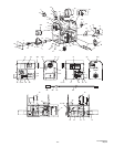
END VIEW
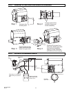
RECOMMENDED GAS CONNECTION POSITIONS WITH 24 FLEXIBLE GAS HOSE
A
B
A
B
Position 1Position 2
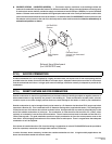
Gas pipe work must
not restrict opening of
hinged service doors.
Alternate Positions
6
150mm
SIDE VIEW
C
Burner Movement
Flexible
Connector
12
(305mm)
Sediment Trap
(Drip Leg)
Optional Second Stage Regulator with
Vent Leak Limiter if required to reduce
the Supply Pressure below 14 W.C.
7 5/8
194mm
Note: When venting a single
heater horizontally through a
combustible outside wall the
vent must pass through a 2
clearance thimble (Air Jet No.
4VT or Ameri-vent No 4EWT
or other thimbles which are
listed by nationally recognized
testing agency.
Attach a vent cap (Breidert No.
4L or equivalent)
Minimum equivalent length of
vent pipe = 5ft (1.5m)
Maximum equivalent length of
vent pipe = 50ft (15m)
Nota: le conduit d'échappement
d'un radiateur simple traversant
un mur combustible doit passer
dans une gaine de 2 po (Air Jet
n° 4VT ou Ameri-vent n° 4EWT
ou autre gaine normalisée par
un organisme d'essai reconnu
à l'échelle nationale.
Poser un capuchon d'évent
(Breidert n° 4L ou équivalent)
Longueur minimale équivalente
du tuyau d'échappement = 1,5m
(5pi)
Longueur maximale équivalente
du tuyau d'échappement = 15m
(50pi)
THIS UNIT EQUIPPED WITH A
2 AMP IN LINE-FUSE FOR
OVERCURRENT PROTECTION
OF CONTROL CIRCUIT
ELECTRIC SHOCK
HAZARD
Disconnect electrical supply
before servicing
Failure to follow these
instructions may result in
death, serious injury or
property damage.
WARNING
42922030 Rev - 11/07
SIDEWALL VENTING ONLY
UN MUR LATÉRAL
AÉRATION
22a
63
57
55
54
58
59 49 59 61
51 56
65 66 67 68
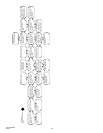
GAS TYPE
SUPPLY PRESSURE
Pression de Sortie
Type de Gaz
MAXIMUM
MINIMUM
MANIFOLD PRESSURE
Pression a lechappement
INPUT Btu/Hr
Consommation Btu / Hr
ORIFICE SIZE
Dimensions bec Veilleuse
MODEL NO.
No. de Modelè
Installation in:
1. Aircraft hangers must be in accordance with the standard for Aircraft Hangers.
ANSI/NFPA 409 (latest edition).
2. Public garages must be in accordance with the standard for parking structures,
ANSI/NFPA 88a (latest edition), or with the standard for repair garages,
ANSI/NFPA 88b (latest edition)
SERIAL NO.
No. de Série
LIGHTING & SHUTDOWN INSTRUCTIONS
1. Turn on gas & electrical supply.
2. Set thermostat to call for heat.
3. Ignition should occur after prepurge.
4. If ignition fails, the unit will spark for approximately 21 seconds
& go into safety lockout. Turn thermostat (or power) off for 60
seconds to take out of lockout.
5. If heater does not light, shut off gas completely for 5 minutes
before attempting to relight.
6. To shut down the heater, turn off the gas & electrical supply.
Infrared Radiant Tube Heater
Radiateur à tuve rayonnant à infrarouge
Gas Fired products Inc. Charlotte, NC
INSTRUCTIONS DALLUMAGE ET DE FERMETURE
1. mettre la valve a gaz et linterrupteur a ON.
2. Creer une demande de chauffage au thermostat.
3. Lallumage devrait se produire apres de prepurge.
4. Si lallumage ne se fait pas, le controle dallumage continu de
produire des etincelles sur une periode de 21 sec. et ensuite
tomber en securite. Mettre le thermostat (ou le courant) en
position darret (OFF) pour une periode de 60 sec. a fin
dinterrompre le processus de securite.
5. Si lappareil ne sallume pas, fermez le gaz completement pour
une period de 5 min. avant deffectuer une nouvelle tentative
dallumage.
6. Pour fermer lappareil, fermez le gaz et le courant electrique.
For indoor installation only
Installer à lintérieur seulement
Vented or Unvented
ELECTRICAL:
ALTITUDE
ANSI Z83.20b / CSA 2.34b - 2003 Tel: 1800 438 4936 e-mail info@spaceray.com
CODE DATE
42848000 Rev. H 10/04
MAX ANGLE:
Max Angle
Electrique
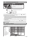
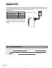
Combustible material must be located outside the clearance dimensions listed.
Ceiling Clearance is 18 (46cm) when installed in an UNVENTED configuration. Ceiling
clearance is 18 (46cm) when the optional U-bend reflectors are not used.
Failure to do so may result in death, serious injury or property damage
Models: PC(S,A)
43344080 10/07
Le dégagement au-dessus de l'appareil doit être d'au moins 46 cm quand l'appareil est installé
SANS ÉCHAPPEMENT. Le dégagement au-dessus de l'appareil doit être d'au moins 46cm
quand les réflecteurs d'angle optionnels ne sont pas utilisés.
D
D
Model No A B C D E F
75 27 6 60 30 48 12
(69cm)(15cm)(152cm)(76cm)(122cm)(30cm)
100 66 6 88 40 66 20
(168cm)(15cm)(224cm)(102cm)(168cm)(51cm)
125 66 6 101 40 66 20
(168cm)(15cm)(257cm)(102cm)(168cm)(51cm)
150 84 6 106 48 84 24
(213cm(15cm)(269cm)(122cm)(213cm)(61cm)
Horizontal
B
C
AA
45 degrees
B
C
E
F
Montage horizontal
Montage à 45°
43344110 03/08
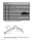
Install the gas flexible hose as shown in the diagram below:
Sharp bends, kinks, twists and tension in the hose may cause failure resulting in a gas leak.
Failure to follow these instructions may result in death, serious injury or property damage.
Position A B C
1 6 3/4 (171mm)9 5/8 (245mm)3 7/8 (99mm)
2 9 1/8 (232mm)7 5/8 (194mm)3 7/8 (99mm)
OPTIONAL LOW VOLTAGE (24V)
THERMOSTAT CONNECTION.
THE RED JUMPER WIRE MUST BE
REMOVED IF MAKING
24V THERMOSTAT CONNECTIONS.
43269010 Rev. A 12/07
11
TUBE INTEGRITY SAFETY SYSTEM
43269020 Rev. B 03/08
In the event of tube failure the wire inside
the sleeve will break. For safety replace
the entire wire assembly including the
sleeve PN 44176010
Patent Pending
The system must be installed with tension
on the spring.
FRAGILE! DO NOT Lift the burner box by
these wires.
Reflector edge.
BURNER SUSPENSION CHAIN
MUST BE USED TO SUPPORT
BURNER BOX. FAILURE TO USE
EYEBOLT SUSPENSION WILL VOID
MANUFACTURERS WARRANTY.
USE A TURNBUCKLE FOR LEVEL
ADJUSTMENT OF BURNER BOX.
43269030 12/07
ATTENTION INSTALLER!
THE GAS CONTROL VALVE IS FACTORY
SET AT OFF POSITION. OPEN THIS
ACCESS PANEL TO TURN THE GAS
VALVE TO ON POSITION. BY THIS
ACTION YOU CERTIFY THAT ALL GAS
CONNECTIONS AND CHECKS COMPLY
WITH WRITTEN I & O INSTRUCTIONS
SHIPPED WITH THIS HEATER.
43269040 12/0743269040 12/0743269040 12/07
43269050 Rev. A 03/08
DANGER
Failure to do so may result in death,
serious injury or property damage
FIRE HAZARD
This access panel must be closed
tightly with all the necessary screws
during operation.
Never operate the heater with the
access panel open or removed.
43269050 Rev. A 03/08
DANGER
Failure to do so may result in death,
serious injury or property damage
FIRE HAZARD
This access panel must be closed
tightly with all the necessary screws
during operation.
Never operate the heater with the
access panel open or removed.