


Form #43343330
May 08 –41–
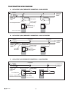
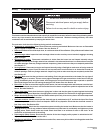
Note
1
: When the PTS / PTU is operated by a thermostat interrupting the line voltage (120V) to the heater then the
post purge function is disabled.
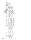
If the flame is not sensed during sequence T3 then the burner will automatically begin re-ignition sequence T2. The
ignition sequence will be repeated three times with a 60 second inter-purge. If the flame is not re-established the
heater will go to lockout.
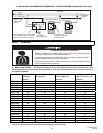
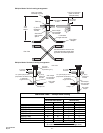
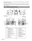
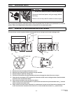
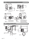
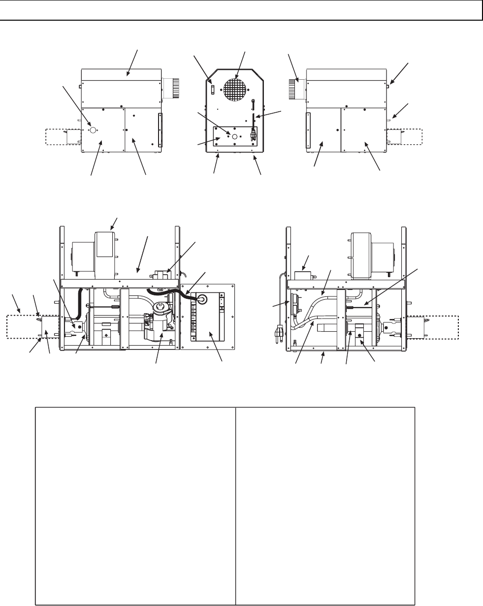
20.0) BURNER COMPONENT LOCATIONS
Legend
:
1 Cabinet Assembly
2 Access Panel - Top
3 Access Panel - Hinged (2 ea)
4 Access Panel - LH Burner
5 Access Panel - RH Burner
6 Air Inlet Screen
7 Gas Inlet Connection - 1/2NPT
8 Power Supply Cord - 120V
9 Burner Sight Glass
10 Indicator Light - Amber (Gas Valve)
11 Indicator Light - Red (Air Switch)
12 Tube Flange Connection
13 Main Burner
14 Flame Screen (200m/BTU units only)
15 Electrode
16 Flame Sensor
17 Main Burner Orifice
18 Air Restrictor Plate
2
9
4
3
6
7
8
10
11
5
12
25
Note: This panel
must remain closed
for burner operation.
Note: This panel
must remain closed
for burner operation.
30
3
32
24
1
26
27
28
29
35
14
15
16
13
17
18
19
22
23
20
33
21
34
31
19 Gas Control Valve
20 Ignition Module
21 Ignition Cable
22 Blower Assembly
23 Transformer - 120/24 VAC
24 Terminal Block/Fishpaper Shield
25 Air Switch
26 Air Sensing Tube (P1+)
27 Air Sensing Tube (P2-)
28 Manifold Pipe
29 Manifold Support Bracket/Clamp
30 Terminal Block (24V thermostat)
31 Terminal Block (TISS connection)
32 Starting Collar
33 Valve Holder Plate
34 Fuseholder/Fuse (2 amp)
35 Combustion Air Plate