


Form #43343330
May 08 –11–
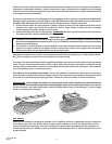
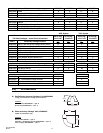
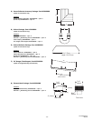
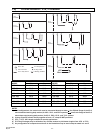
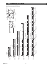
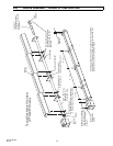
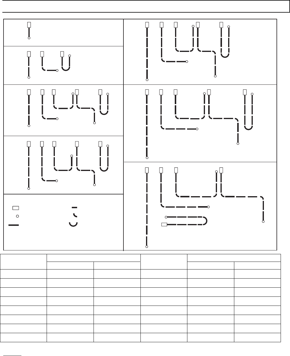
7.0) TYPICAL LAYOUTS – PTU / PTS Series
Burner Box
Flue Termination
10 FT. Body Section
30 FT.
SYSTEM
40 FT.
SYSTEM
20 FT.
SYSTEM
50 FT.
SYSTEM
60 FT.
SYSTEM
70 FT.
SYSTEM
10FT.
SYSTEM
5 FT. Body Section
90 Deg. Elbow
180 Deg. U-Bend
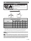
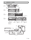
LEGEND
EMITTER LENGTH BODY LENGTH
MODEL
Min. Max.
MODEL
Min. Max.
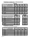
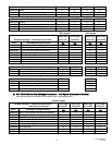
PTS 40 10 Ft. 20 Ft. PTU 40 10 Ft. 10 Ft.
PTS 50 20 Ft 30 Ft. PTU 50 10 Ft. 15 Ft.
PTS 75 20 Ft. 30 Ft. PTU 75 10 Ft. 15 Ft
PTS 100 30 Ft. 40 Ft. PTU 100 15 Ft. 20 Ft.
PTS 125 30 Ft 50 Ft. PTU 125 15 Ft. 25 Ft.
PTS 150 40 Ft. 60 Ft. PTU 150 20 Ft. 30 Ft.
PTS 175 50 Ft. 70 Ft. PTU 175 25 Ft. 35 Ft.
PTS 200 50 Ft. 70 Ft. PTU 200 25 Ft. 35 Ft.
NOTES:
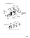
1) In all configurations, the control unit must be connected directly to either a) the 24-hole flange of the 10 ft.
aluminized steel starting body section (for 10 ft., 20 ft., and 30 ft. systems) or b) the 6-hole flange of the 10 ft.
alumi-therm steel starting body section (for 40 ft., 50 ft., 60 ft., and 70 ft. systems.
2) Joining of two 90º elbows directly together to form a “Z” shape IS NOT permitted.
3) PTS / U 175 - 40 ft length available for special applications.
4) 5 Ft. Body Packages may be utilized on any of these heaters to yield heater lengths from 15 ft. to 70 ft.
5) Any configuration of components not shown in the illustrations may be used except as noted in 1 and 2