


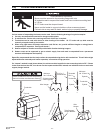

Form #43343330
May 08 –21–
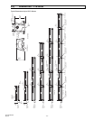
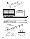
MODEL 2 Ft. Turbulator Sections
PTS/U 40 4
PTS/U 50 5
PTS/U 75 5
PTS/U 100 3
PTS/U 125 7
PTS/U 150 4
PTS/U 175 0
PTS/U 200 1
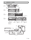
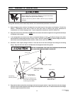
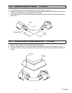
10.3) ADDING REFLECTORS
1. Slide the reflectors on the tube support/hanger brackets and through the wire hangers.
2. The tube at the coupling joints must be covered. Slide the reflectors together and provide an overlap of two (2”)
inches for the first reflector overlap after the control unit. All remaining reflector overlaps will be approximately
one (1”) inch. This will allow for the natural expansion and contraction of the heater when in operation. Note: The
heaters can expand and contract up to 1-3/4” of an inch.
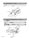
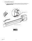
3. Secure the reflectors as shown in Detail “A” using #10 x 1/2” self-drilling sheet metal screws at each tube
support/hanger bracket.
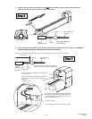
REFLECTOR
OVERLAP
(offset from tube
hanger support brackets)
2 OVERLAP
1 OVERLAP
1 OVERLAP
DETAIL A
REFLECTOR
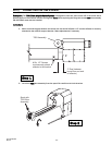
40 FT SYSTEM SHOWN
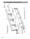
3 Gap
(between burner box
and reflector)
FLUE
TERMINAL
BURNER
BOX
DETAIL A
#10 x 1/2 SHEET
METAL SCREW
(Typical all tube
hanger/
support brackets.)
REFLECTOR
OVERLAP
(positioned over tube
hanger support brackets)
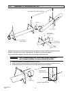
DETAIL B
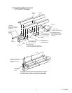
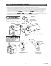
CORRECT INSTALLATION INCORRECT INSTALLATION
Burner Box
Suspension
Chain
DETAIL B
The reflector overlap must be
able to slide at this joint for
expansion of the heater
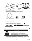
Turbulators
The PTS / U 40 has one stainless steel
turbulator. This must be installed
closest to the burner.
Failure to do so may result in
deterioration of the turbulator material
and invalidate the warranty.
ASSEMBLY HAZARD