


Page 14
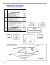
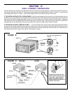
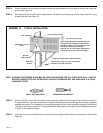
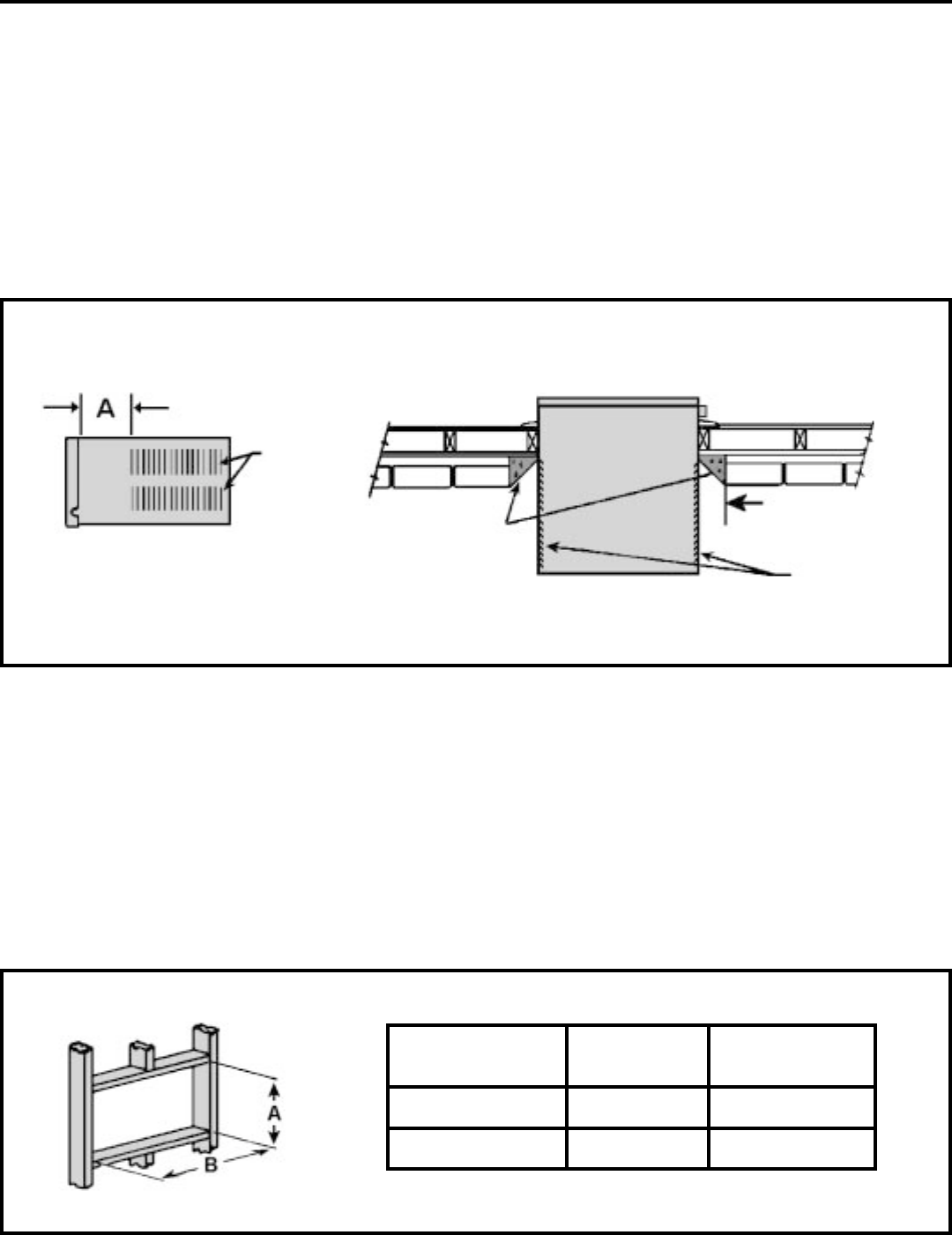
NOTE: THESE DIMENSIONS ARE FOR FINISHED HOLE SIZE
HOLE SIZE REQUIREMENTS
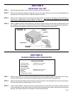
SECTION V — SHELL INSTALLATION
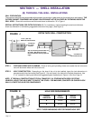
(B) THROUGH–THE–WALL INSTALLATIONS
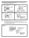
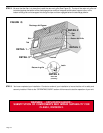
Condenser air
Intake louvers
2" (51 mm) minimum
Both sides
Top view showing beveled sides for
air intake. Wall below unit must
also be beveled to assure proper tilt
angle.
Condenser
Air intake
Louvers
15 1/8 " (384 mm)
Maximum wall thickness
FIGURE J
EXTRA THICK WALL CONSTRUCTION
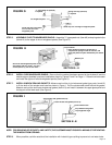
FIGURE K
STEP 1. CHECKING WIRING AND PLUMBING: Check all wiring and plumbing inside and outside the wall to be sure
none will be broken where the hole is to be cut.
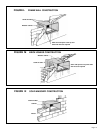
STEP 2. HOLE CONSTRUCTION: Depending on the size of the unit to be installed, layout the hole dimensions in
accordance with the chart below (See Figure K). Cut and frame in the hole to the finished dimensions. Use
2" x 4" material for framing and follow the suggested typical installations in Figure L, M or N on Page 15.
NOTE: IF THE WALL CONSTRUCTION IS TYPICAL FRAME OR 2 X 4 STUDDING WITH BRICK OR STONE
VENEERS, LOCATE THE HOLE NEXT TO ONE OF THE STUDS. FOR MASONRY, CONCRETE OR CINDER BLOCK
WALLS, LOCATE THE HOLE FOR CONVENIENCE.
FINISHED SMALL MEDIUM
DIMENSION CHASSIS CHASSIS
A 16-3/16" 18-3/16"
B 26-3/16" 26-3/16"
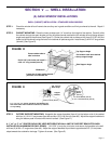
WALL PREPARATION:
The maximum wall thickness permissible without special construction is determined by the model size to be installed. THE
OUTSIDE CABINET CONDENSER AIR INTAKE LOUVERS MUST NOT BE BLOCKED BY EXTENDING INSIDE THE
WALL AREA. Observe the maximum wall thickness shown as dimension "A" in Figure J.
SPECIAL INSTRUCTIONS FOR EXTRA THICK WALLS: For installation in walls exceeding the maximum thickness
shown as dimension A, the following suggested construction may apply. (See Figure J).