


8
www.retroaire.com
The Right Fit For Comfort
INSTALLATION INSTRUCTIONS
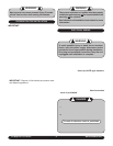
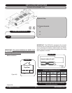
1. Take unit out of packaging.
2. Slide unit into wall sleeve. The supply duct on the cool
-
ing chassis should line up with the supply vent on the
room cabinet. The weather angles should require no
adjustment.
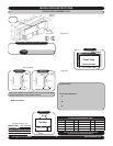
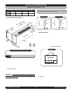
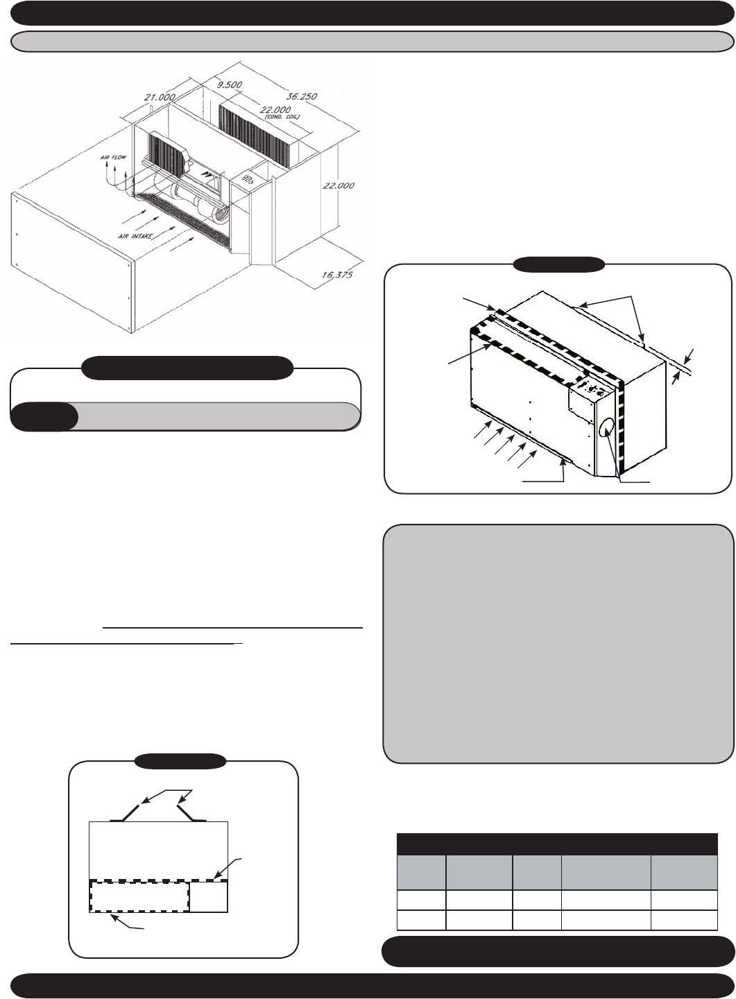
3. Make sure baffles come in contact with the outdoor
louver.
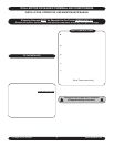
IMPORTANT:
Baffles and open cellfoam tape seals
are factory installed on the RC
12 . Baffles fill the gap
between the rear of the chassis and the outdoor louver
and prevent the air from recirculating. Consult the factory
if baffles supplied are not deep enough to accommodate
wall sleeve application as system efficiency and reliability
are dependent on proper air flow. (
Figure A3)
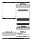
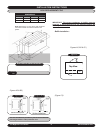
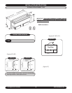
IMPORTANT: If adjoining room conditioning is required, the
RC12 is able to discharge to the right and left by utilizing
the four-inch knockouts
(Figure B3) on either side of the
evaporator compartment using 4” flex duct.
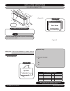
3. Once confident that all seals are the correct size and in
the proper location and the correct baffles are attached
to the condenser coil and in the proper orientation, slide
unit into final position and tighten any tie down bolts or
screws as necessary.
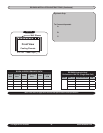
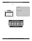
RC12 REPLACEMENT PTAC
*Refer to the charts on page 23 for electrical and
optional electric heat specifications.
RC12 PERFORMANCE DATA*
UNIT
SIZE
COOLING
BTUH
EER
EVAP CFM
HIGH/LOW
FRESH
AIR CFM
12 12,200 10 390/340 40/35
15 15,500 9 440/390 40/35
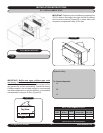
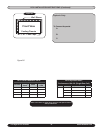
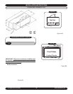
Hydronic Only: Remove the 2-position connector as-
sembly from kit bag supplied with unit (this will have 2
yellow wires attached). Connect this 2-position connec
-
tor to the 2-position connection located on the bottom
of the control box panel.
To Connect Aquastat:
A. Remove the black jumper wire located on the
bottom panel of the control box (this is also ter-
minated with a 2-position connector).
B. Cut the jumper wire in the middle and splice the
aquastat to the jumper.
C. Place the connecter back into original location.
Refer to wire diagram on the unit for details.
4. Connect line cord.
5. See Final Inspection and Startup on page 20.
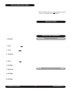
• 1 Installation Manual
HYDRONIC
ONLY
• 1ea. 2-Position Connector & Pin Mate
• 14AWG Black Wire
RC12 INSTALLATION KIT
Figure B3
Left and Right
Condenser Baffles
5/8” Ref.
Removeable Filter
Air Intake
4” Knockout
1” X 1/2”
Open Cell
Foam Tape
1” x 1” Open Cell
Foam Tape
Figure A3
1” X 1/2” Supply Air
Duct Foam Tape
Baffles-Directed Inward
Toward Coil
1” X 1 ”
Open Cell
Foam Tape