


21
www.retroaire.com
The Right Fit For Comfort
controls will power a normally closed valve that is the
same voltage as the unit (ex: a unit rated 208/230
V
will power a 208/230
V normally closed valve). Be sure
to check the wiring diagram (located on the unit) and
voltage application for the specific unit. Other valve
configurations and voltage options are available. Con
-
sult Technical Service if the unit voltage does not match
your valve application.
A. Place system switch in the “HEAT” position.
B. Turn thermostat knob counter-clockwise. Motorized valve
should open and allow hot water to run through the coil. The
indoor fans will run, blowing air through the hydronic coil.
C. Check room comfort level as outlined under “Heating
Cycle - Electric.”
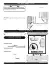
MOTORIZED FRESH AIR DAMPER (Optional): The
optional motorized fresh air damper allows the operator
to move fresh air into the space to be conditioned. This is
done by placing the damper door switch in the
“YES” posi-
tion, opening the damper door and allowing fresh air to be
moved into the space. To stop the flow of fresh air, simply
place the switch in the “NO” position.
CHANGEOVER T-STATS (Heat Pump Only): On units with a
changeover thermostat, the compressor can run to an outdoor
temperature of 40° F and then shut off. Electric heat will then
energize and assume the heating demand until the tempera
-
ture of the outdoor air rises to approximately 50° F.
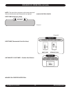
FAN CYCLE SWITCH: This option allows the operator of the
Dual Motor PTAC to have the evaporator fan cycle or run con-
tinuously. With the switch in the cycling position the evaporator
fan will only run when the unit is calling for heat or cooling. When
the switch is in the “CONSTANT” position, the evaporator fan
will run continuously unless the unit is physically turned off.
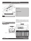
CONDENSATE REMOVAL: The Dual Motor PTAC has a
drain connection at each end of the condensate drain pan.
This allows the condensate to drain through the bulkhead
to the area near the condenser fan. The condenser fan has
a slinger ring that picks up the condensate and slings it on
the hot condenser coil where it evaporates. On heat pump
models condensate can form on the outdoor coil during
the heat pump cycle. A temperature sensitive valve in the
base pan will allow condensate to flow to an internal piping
system or external drain kit (supplied by others).
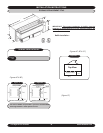
AQUASTAT CONNECTION (Optional): All straight cool
Dual Motor PTACs are supplied with a standard high volt
aquastat connection. The connection is located on the bot-
tom or side with a black jumper wire installed in molex. To
wire option take jumper wire and cut in half. Then connect
2 field supplied wires to the cut ends of jumper and wire
to aquastat (see wiring diagram for more information). If
option is not being used simply leave jumper wire con-
nected to unit.
IMPORTANT: The room temperature must be above
65º F for the compressor to operate.
3. Place system switch in the “OFF” position. All operation
should stop.
HEATING CYCLE - Electric:
1. Place system switch in the “HEAT” position.
2. Rotate thermostat knob counter-clockwise until the
indoor fans start running and the electric coil starts
emitting heat. The condenser fans do not run during
the heating cycle unless the chassis is a heat pump.
After the unit starts running and the area gets warmer,
turn the thermostat knob clockwise until a slight click
is heard and the electric heater turns off. If a warmer
room temperature is desired, continue turning the knob
counter-clockwise and let the unit continue operating. If
a cooler room temperature is desired, rotate the thermo-
stat knob clockwise until the electric heater cycles off.
IMPORTANT: Room temperature must be below 85º F
to energize the heater.
3. Place system switch in the “OFF” position. All operation
should stop.
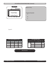
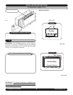
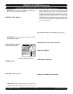
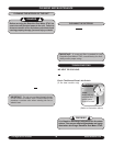
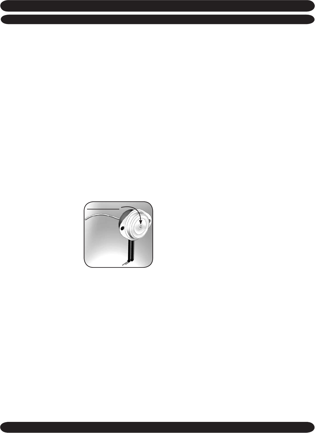
Manual Reset Limit Switch
(5 Kw heat models only) In the
event the limit switch opens
and de-energizes the electric
heat, the limit switch will need
to be manually reset.
• To reset switch remove the
control box cover.
• Locate the limit switch.
• Push in the reset button on
the face of the switch. (Refer to illustration above)
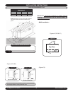
HYDRONIC COIL: The coil with the old unit can be located
in the subbase, under the chassis in a special attachment,
or above the chassis in a special attachment. It is neces
-
sary to know where the coil is to be located and the physical
size of the coil so the right coil can be supplied if ordered for
replacement. The coil is shipped loose for field installation.
It should be installed in the same manner as the coil it is
replacing. When the hydronic coil is not replaced, installation
of the chassis should follow the instructions in this manual.
HEATING CYCLE -
Hydronic: All straight cool Dual Motor
PTACs are equipped with a field supplied hydronic heat op
-
tion. The unit is provided with a two-position molex plug for
motor valve connection. To wire this option, take the molex
plug connector with (2) yellow wires from the kit and plug
it into the molex on the unit. Then wire the opposite end of
the molex to the motorized valve in the hydronic circuit.
IMPORTANT: Make sure the motor valve is rated for the
correct voltage. M
ost RetroAire units with unit mount
UNIT MOUNTED THERMOSTAT OPERATIONAL INSTRUCTIONS (Continued)
SEQUENCE OF OPERATION (Continued)
Reset Button
*Note:
Button will pop
out when limit
switch opens.
Push in to reset.