


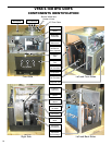
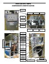
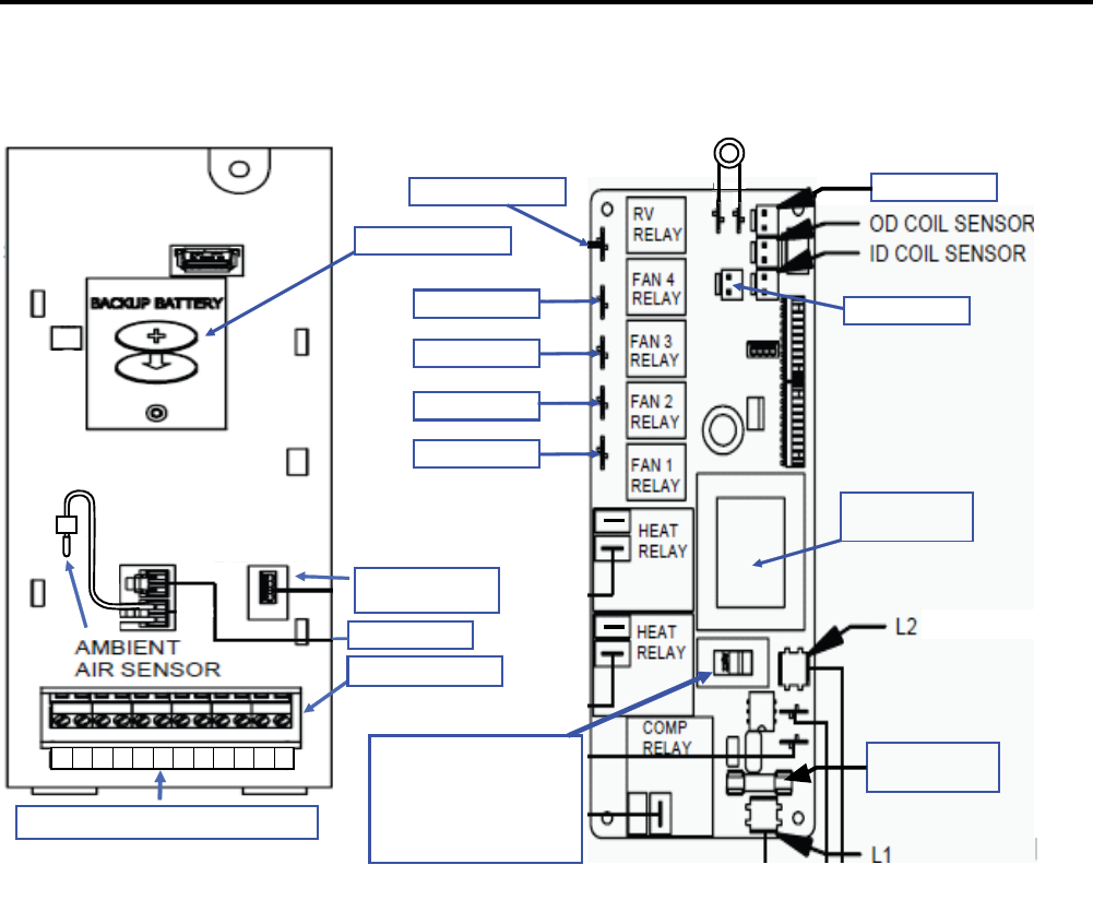
ELECTRONIC CONTROL BOARD COMPONENTS IDENTIFICATION
AND TESTING (Continued) (See wiring diagrams pages 41-46)
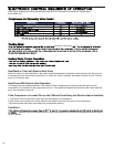
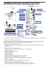
Front
Sample board for Kuhl+ unit
Back
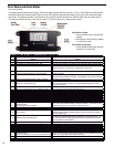
VPAK 24K
High Pressure Switch
Reversing Valve
High Speed
Low Speed
T-stat Terminals
Transformer voltage
Selector Switch
115/230 Volts
Ensure it is set at
230VAC
Not Used
Not Used
Not Used
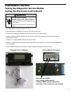
Diagnostic
Service Module
Transformer
115/230 Volts
Fuse 10 Amps
250 VaC
Low Voltage Interface Connection
FP F2 F1 D2 D1 C GHGL B Y W R
(Blue)
(Green)
Not Used
Not Used
Not Used
1. Test for power at L1 and L2 for 208/230 VAC. (Ensure the transformer voltage selector switch is set for 230 VAC)
2. Test the 10 amp/250 VAC fuse for continuity.
FOR THE FOLLOWING TESTS, ENSURE THE UNIT IS IN THE APPROPRIATE SETTINGS FOR THE TEST
BEING PERFORMED. ENSURE THERE ARE NO ERROR CODES ACTIVE.
3. Testing the compressor relay and heat relays:
Test for power in and power out. If there is power in and no power out, replace the electronic control board.
(208/230 to L2)
4. Testing the fan and reversing valve relays:
Test for power at the reversing valve and fan relays 1 or 3. (208/230 to L2)
5. Testing the transformer:
Test the low voltage terminal strip at:
R and C for 24 VAC
F2 and F1 for 24 VAC
D2 and D1 for 24 VAC
Test the service module connector for 5 VDC (see prior page)
Test the connectors for the thermistors for up to 5 VDC
If there is no voltage at any of the above, replace electronic control board.
6. Testing the thermistors:
Disconnect the thermistor and test for resistance value (see page 35)
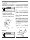
7. Testing the high pressure switch (VPAK 24K only)
Test for 24 VAC at board, if there is no voltage, replace the electronic control.
Test the pressure switch for continuity, if none, replace it (switch is normally closed)
18