


9
Electrical Rating Tables
NOTE: Use copper conductors ONLY
Wire sizes are per NEC. Check local codes for
overseas applications
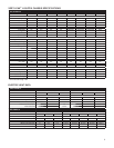
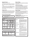
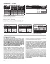
Recommended branch circuit wire sizes*
Nameplate maximum circuit
breaker size
AWG Wire size**
15A 14
20A 12
30A 10
AWG — American Wire Gauge
* Single circuit from main box
** Based on copper wire, single insulated conductor at 60°C
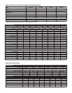
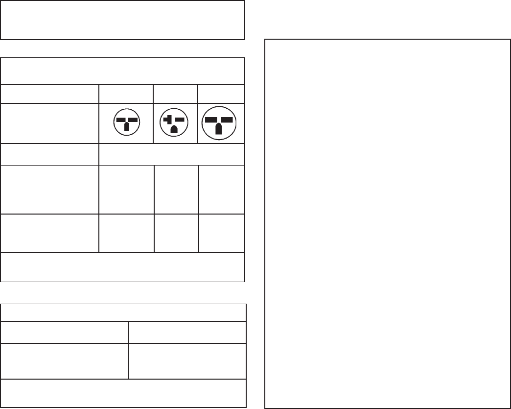
250 V Receptacles and Fuse Types
AMPS 15 20 * 30
RECEPTACLE
MANUFACTURER PART NUMBERS
Hubbell 5661 5461 9330
P & S 5661 5871 5930
GE GE4069-1 GE4182-1 GE4139-3
Arrow-Hart 5661 5861 5700
TIME-DELAY TYPE
FUSE 15 20 30
(or HACR circuit breaker)
HACR — Heating, Air Conditioning, Refrigeration
* May be used for 15 Amp applications if fused for 15 Amp
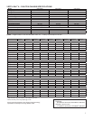
A through D Suffi x
Units Only
Electrical Requirements
NOTE: All fi eld wiring must comply with
NEC and local codes. It is the
responsibility of the installer to
insure that the electrical codes are
met.
Wire Size Use ONLY wiring size recommended
for single outlet branch circuit.
Fuse/Circuit Use ONLY type and size fuse or
HACR circuit breaker
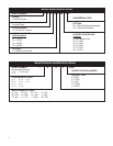
Breaker Indicated on unit's rating plate (See
sample on page 6).
Proper current protection to the unit
is the responsibility of the owner.
Grounding Unit MUST be grounded from branch
circuit to unit, or through separate
ground wire provided on permanently
connected units. Be sure that branch
circuit or general purpose outlet is
grounded.
Wire Sizing Use recommended wire size given in
the tables below and install a single
branch circuit. All wiring must comply
with local and national codes. NOTE:
Use copper conductors only.
Electrical Supply
WARNING: Electrical shock hazard.
Turn OFF electric power at fuse box or service panel
before making any electrical connections and ensure a
proper ground connection is made before connecting line
voltage.
All electrical connections and wiring MUST be installed by
a qualifi ed electrician and conform to the National Electrical
Code and all local codes which have jurisdiction.
Failure to do so can result in property damage, personal
injury and/or death.
Supply Circuit
The system cannot be expected to operate correctly unless
the system is properly connected (wired) to an adequately
sized single branch circuit. Check the installation manual
and/or technical data for your particular unit and/or strip
heaters to determine if the circuit is adequately sized.
Supply Voltage
To insure proper operation, supply voltage to the system
should be within fi ve (5) percent (plus or minus) of listed
rating plate voltage.
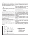
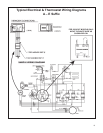
Control (Low) Voltage
To insure proper system operation, the transformer
secondary output must be maintained at a nominal 24 volts.
The control (low) voltage transformer is equipped with
multiple primary voltage taps. Connecting the primary,
(supply) wire to the tap (i.e., 208 and 240 volts) that most
closely matches the MEASURED supply voltage will insure
proper transformer secondary output is maintained.
Supply Voltage
Supply voltage to the unit should be a nominal 208/230 volts.
It must be between 197 volts and 253 volts. Supply voltage
to the unit should be checked WITH THE UNIT IN
OPERATION. Voltage readings outside the specifi ed range
can be expected to cause operating problems. Their cause
MUST be investigated and corrected.
Electrical Ground
GROUNDING OF THE ELECTRICAL SUPPLY TO ALL
UNITS IS REQUIRED for safety reasons.