


14
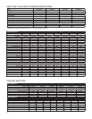
Indoor Blower - Airfl ow
The current Vert-I-Pak 9, 12, & 18 use a dual shaft, permanent
split capacitor, single speed motor to drive indoor blower and
outdoor fan. Earlier model VERT-I-Pak units used 2-speed
motors. The Vert-I-Pak 24 uses an individual, single shaft,
permanent split capacitor, single speed motor for the indoor
blower, and a separate motor drives the outdoor fan.
Different size (HP) motors and/or different diameter blower
wheels are used in different models to obtain the required
airfl ow.
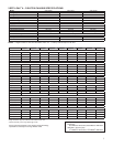
Condenser Fan Motors
The current Vert-I-Pak 9, 12, & 18 units use a dual shaft,
permanent split capacitor, single speed motor to drive indoor
and outdoor fan. Earlier models used a 2-speed motor. The
Vert-I-Pak 24 uses and individual, single shaft, permanent
split capacitor, single speed motor for the outdoor fan, with a
separate motor driving the indoor blower.
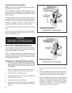
Blower Wheel Inspection
Visually inspect the blower wheel for the accumulations
of dirt or lint since they can cause reduced airfl ow. Clean
the blower wheel of these accumulations. If accumulation
cannot be removed, it will be necessary to remove the
blower assembly from the unit for proper wheel cleaning.
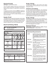
Cooling
A nominal 400 (350-450 allowable) CFM per ton of airfl ow
is required to insure proper system operation, capacity,
and effi ciency. Factory-set blower speeds should provide
the proper airfl ow for the size (Cooling capacity) of the unit
when connected to a properly sized duct system.
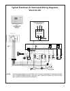
Cooling (VEA/VHA 24)
When the thermostat is set for cooling mode (SYSTEM
switch set to COOL and FAN switch to AUTO) a rise in room
temperature will make It also causes a 24-volt signal on the
“Y” thermostat conductor through the high pressure and low
ambient switches energizing the compressor relay, turning
on the compressor and outdoor fan motor. A 24-volt signal
on the “G” thermostat terminal to the Fan Relay, turning on
the indoor blower motor.
Heating (Electric)
When using electric heaters, select the blower speed that
provides adequate airfl ow across the elements to prevent
overheating and cycling on limit and/or premature failure.
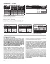
CHECK THE EXTERNAL STATIC PRESSURE, and then
consult the AIR FLOW DATA to determine the ACTUAL air
fl ow delivered for the factory selected fan speed. This will
be especially important on change-outs using an existing
duct system that may not have been properly sized to
begin with.
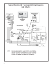
Heating (VEA/VHA 24)
When the thermostat is set for heating mode (System switch
set to HEAT and FAN switch to AUTO) it will make a 24-
volt signal on the “B” thermostat terminal to energize the
Reversing Valve Relay. A drop in room temperature, will
make a 24-volt signal on the “W” thermostat terminal to the
Defrost Thermostat, and “G” thermostat terminal to the Fan
Relay. The Defrost Thermostat will determine whether the
unit should run in Heat Pump, or Electric Heat, based on the
outdoor temperature. (See Defrost Thermostat page 24)
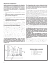
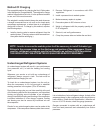
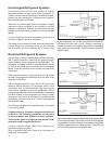
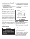
External Static Pressure
External Static Pressure can best be defi ned as the pressure
difference (drop) between the Positive Pressure (discharge)
and the Negative Pressure (intake) sides of the blower.
External Static Pressure is developed by the blower as a
result of resistance to airfl ow (Friction) in the air distribution
system EXTERNAL to the VERT-I-PAK cabinet.
Resistance applied externally to the VERT-I-PAK (i.e. duct
work, coils, fi lters, etc.) on either the supply or return side
of the system causes an INCREASE in External Static
Pressure accompanied by a REDUCTION in airfl ow.
External Static Pressure is affected by two (2) factors.
1. Resistance to Airfl ow as already explained.
2. Blower Speed. Changing to a higher or lower blower
speed will raise or lower the External Static Pressure
accordingly.
These affects must be understood and taken into consideration
when checking External Static Pressure/Airfl ow to insure that
the system is operating within design conditions.
Operating a system with insuffi cient or excessive airfl ow
can cause a variety of different operating problems.
Among these are reduced capacity, freezing evaporator
coils, premature compressor and/or heating component
failures. etc.
System airfl ow should always be verifi ed upon completion
of a new installation, or before a change-out, compressor
replacement, or in the case of heat strip failure to insure
that the failure was not caused by improper airfl ow.