


15
Checking External Static Pressure
The airflow through the unit can be determined by
measuring the external static pressure of the system, and
consulting the blower performance data for the specifi c
VERT-I-PAK.
1. Set up to measure external static pressure at the
supply and return air.
2. Drill holes in the supply duct for pressure taps, pilot
tubes or other accurate pressure sensing devices.
3. Connect these taps to a level inclined manometer
or Magnehelic gauges.
4. Ensure the coil and fi lter are clean, and that all the
registers are open.
5. Determine the external static pressure with the
blower operating.
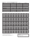
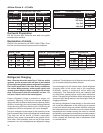
6. Refer to the Air Flow Data for your VERT-I-PAK
system to fi nd the actual airfl ow for factory-selected
fan speeds.
7. If the actual airfl ow is either too high or too low, the
blower speed will need to be changed.
8. Select a speed, which most closely provides the
required airfl ow for the system.
9. Recheck the external static pressure with the
new speed. External static pressure (and actual
airfl ow) will have changed to a higher or lower value
depending upon speed selected. Recheck the actual
airfl ow (at this "new" static pressure) to confi rm
speed selection.
10. Repeat steps 8 and 9 (if necessary) until proper
airfl ow has been obtained.
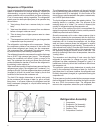
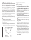
EXAMPLE: Airfl ow requirements are calculated as follows:
(Having a wet coil creates additional resistance to airfl ow.
This addit ional resistance must be taken into consideration
to obtain accurate airfl ow information.
1 ½ TON SYSTEM ( 18,000 Btu)
Operating on high speed @ 230 volts with dry coil
measured external static pressure .20
Air Flow = 500 CFM
In the same SYSTEM used in the previous example but
having a WET coil you must use a correction factor of
.94 (i.e. 500 x .94=470 CFM) to allow for the resistance
(internal) of the condensate on the coil.
It is important to use the proper procedure to check external
Static Pressure and determine actual airfl ow. Since in
the case of the VERT-I-PAK, the condensate will cause
a reduction in measured External Static Pressure for the
given airfl ow.
It is also important to remember that when dealing with
VERT-l-PAK units that the measured External Static
Pressure increases as the resistance is added externally
to the cabinet. Example: duct work, fi lters, grilles.
Checking Approximate Airfl ow
If an inclined manometer or Magnehelic gauge is not
available to check the External Static Pressure, or the
blower performance data is unavailable for your unit,
approximate air fl ow call be calculated by measuring the
temperature rise, then using tile following criteria.
KILOWATTS x 3413
= CFM
Temp Rise x 1.08
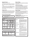
Electric Heat Strips
The approximate CFM actually being delivered can be
calculated by using the following formula:
DO NOT simply use the Kilowatt Rating of the heater (i.e.
2.5, 3.4, 5.0) as this will result in a less-than-correct airfl ow
calculation. Kilowatts may be calculated by multiplying
the measured voltage to the unit (heater) times the
measured
current draw of all heaters (ONLY) in operation to obtain
watts. Kilowatts are than obtained by dividing by 1000.
EXAMPLE: Measured voltage to unit (heaters) is 230 volts.
Measured Current Draw of strip heaters is 11.0 amps.
230 x 11.0 = 2530
2530/1000 = 2.53 Kilowatts
2.53 x 3413 = 8635
Supply Air 95
°
F
Return Air 75
°
F
Temperature Rise 20
°
20 x 1.08 = 21.6
8635
= 400 CFM
21.6
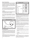
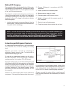
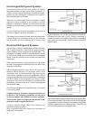
IMPORTANT: FLEX DUCT CAN COLLAPSE AND
CAUSE AIRFLOW RESTRICTIONS. DO NOT
USE FLEX DUCT FOR: 90 DEGREE BENDS, OR
UNSUPPORTED RUNS OF 5 FT. OR MORE.