


16
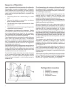
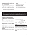
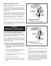
Ductwork Preparation
Pull the fl ex duct tight. Extra fl ex duct slack can greatly
increase static pressure
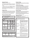
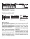
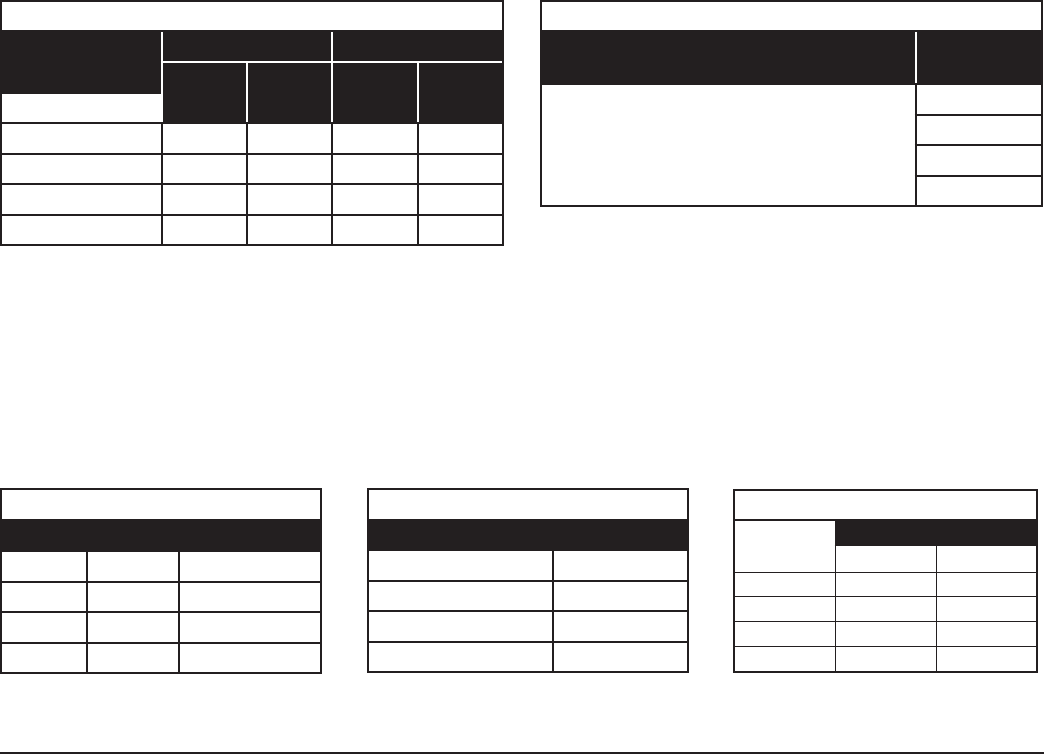
Explanation of charts
Chart A is the nominal dry coil VERT-I-PAK CFMs. Chart
B is the correction factors beyond nominal conditions.
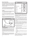
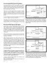
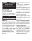
Refrigerant Charging
Note: Because the earlier model Vert-I- Paks are sealed
systems, service process tubes will have to be installed.
First install a line tap and remove refrigerant from system.
The H suffi x model Vert-I-Paks have factory installed ser-
vice values. Make necessary sealed system repairs and
vacuum system. Weigh in charge according to the unit data
plate. Crimp process tube line and solder end shut. Do
not leave a service valve in the sealed system.
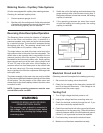
Proper refrigerant charge is essential to proper unit
operation. Operating a unit with an improper refrigerant
charge will result in reduced performance (capacity) and/or
effi ciency. Accordingly, the use of proper charging methods
during servicing will insure that the unit is functioning as
designed and that its compressor will not be damaged.
Too much refrigerant (overcharge) in the system is just as
bad (if not worse) than not enough refrigerant (undercharge).
They both can be the source of certain compressor
failures if they remain uncorrected for any period of time.
Quite often, other problems (such as low air fl ow across
evaporator, etc.) are misdiagnosed as refrigerant charge
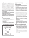
problems. The refrigerant circuit diagnosis chart will assist
you in properly diagnosing these systems.
An overcharged unit will at times return liquid refrigerant
(slugging) back to the suction side of the compressor
eventually causing a mechanical failure within the
compressor. This mechanical failure can manifest itself
as valve failure, bearing failure, and/or other mechanical
failure. The specifi c type of failure will be infl uenced by the
amount of liquid being returned, and the length of time the
slugging continues.
Not enough refrigerant (Undercharge) on the other hand,
will cause the temperature of the suction gas to increase
to the point where it does not provide suffi cient cooling for
the compressor motor. When this occurs, the motor winding
temperature will increase causing the motor to overheat
and possibly cycle open the compressor overload protector.
Continued overheating of the motor windings and/or cycling
of the overload will eventually lead to compressor motor
or overload failure.
Airfl ow Charts A – D Suffi x
Chart A CFM @ 230 Volts - DRY COIL
Model
—
>
V(E,H)A09/A12 V(E,H)A18
Fan Speed
—
>
High
CFM
Low
CFM
High
CFM
Low
CFM
ESP (in water)
0.00 N/A 427 N/A 517
0.10 411 387 510 480
0.20 373 347 500 470
0.30 327 310 490 460
Chart B Correction Factors
To Correct for:
Correction
Factor
230 Volts 1.00
208 Volts 0.97
Dry Coil 1.00
Wet Coil 0.94
Chart A – CFM
Model 18000 12000 / 9000
.00 520 420
.10 510 410
.20 500 370
.30 490 330
Chart B – Correction Multipliers
Correction Multipliers for:
230V 1.00
208V 0.97
Heating 1.00
Cooling 0.95
All values listed are inches W.C. with a wet
indoor coil with fi lter installed.
Chart C – VE/VHA CFM
VEA/VHA24K
Low High
.1" ESP 750 815
.2" ESP 725 780
.3" ESP 700 745
.4" ESP 675 700