17
920-087-04 (3-05)
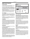
Digital Control Operation
Temperature Display
The Friedrich digital PTAC is shipped from the factory to display
the desired room temperature on the LED readout.
The unit can be confi gured to display the room temperature by
simultaneously pressing the ‘
Cool
’ and ‘
High Fan’
buttons
for three seconds the display will show an ‘
R
’ for one seconds
to acknowledge the change. The unit will display the setpoint
whenever the ‘Temp’ or buttons are pressed and then
switch back to room temperature.
To revert back to displaying the setpoint only press the ‘
Cool
’ and
‘
Low Fan’
buttons for three seconds simultaneously, the unit will
display an ‘
S
’ for one seconds to acknowledge the change.
ºF vs. ºC Display
The unit is factory confi gured to display all temperatures in
degrees Fahrenheit (
º
F
). To switch to degrees Celsius press
the ‘
Fan Only’
and ‘Low Fan’ buttons simultaneously for three
seconds. The display will show a ‘
C
’ as acknowledgement of
the change.
To revert back to
º
F press the ‘
Fan Only’
and ‘
Low Fan’
buttons
simultaneously for three seconds. The display will show an ‘
F
’ as
acknowledgement of the change.
Cooling Mode
Pressing the ‘
Cool
’ button while the unit is in any mode, including
off, will put the unit into cooling mode. Adjust the temperature
readout to the desired room temperature and the unit will cycle
the compressor on and off to maintain a comfortable room. The
compressor will come on anytime that the room temperature
is 1.8°F above the desired temperature. The fan operation is
dependent on the fan mode selected, either continuous or cycling.
See page 16 for fan cycle control.
Heating Mode
Pressing the ‘Heat’ button while the unit is in any mode, including
off, will put the unit into heating mode.
Heat Pump Models (PDH)
When the ‘Heat’ button is pressed initially the unit will energize
the electric resistance heat to quickly bring the room to the
set temperature. When the desired room temperature falls
1.8°F below the desired set temperature the unit will cycle the
compressor on and operate as a heat pump to maintain the room
temperature while running more effi ciently than resistance heat
only models. If the room temperature should fall more than 5°F
from the set temperature the unit will run the resistance heater.
The fan operation is dependent on the fan mode selected, either
continuous or cycling. Dip switch 5 controls the fan mode, see
page 16 for setting.
When the outdoor coil temperature falls below 30°F for more than
2 minutes the unit will operate the resistance heaters and not the
compressor. When the outdoor coil temperature reaches 45°F
the compressor will be allowed to operate again.
Heat/Cool Models (PDE)
After pressing the ‘Heat’ button, adjust the temperature readout to
the desired room temperature and the unit will cycle the resistance
heat on and off to maintain a comfortable room. The heater will
come on anytime that the room temperature is 1.8°F below the
desired temperature. The fan operation is dependent on the fan
mode selected, either continuous or cycling. Dip switch 5 controls
the fan mode, see page 16 for setting.
Emergency Heat Operation
In the event of a compressor failure in heat pump mode the
compressor may be locked out to provide heat through the
resistance heater. This feature ensures that even in the unlikely
event of a compressor failure the room temperature can be
maintained until the compressor can be serviced. Dip switch 7
controls the emergency heat setting, see page 16.
Fan Mode
Fan Only
Pressing the ‘
Fan Only
’ button will run the fan to allow for air
circulation in the room without operating the compressor or
heater regardless of the room or set temperature. The fan speed
selection is made by pressing either the ‘
High Fan
’ or ‘
Low
Fan
’ button.
Cycle/Continuous
The owner may choose between fan cycling or fan continuous
mode based on property preference. (Note: Even heat
monitoring and quiet start/stop fan delay only operate in fan
cycle mode) Fan continuous mode is used to keep constant
airfl ow circulation in the room during all times the unit is ‘ON’.
Fan cycle will conserve energy by only operating the fan while
the compressor or electric heater is operating. Dip switch 5
controls the fan mode, see page 16 for setting.
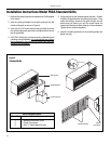
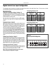
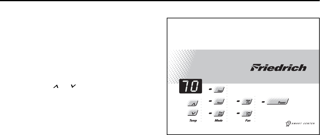
Figure 12
Digital Control Panel


