


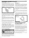
HEATING ELEMENT (See Figure 25)
All heat pumps and electric heat models are equipped with
a heating element with the exception of models starting
with YS09. The “YS” and “ES” models are equipped with a
3.3 KW element. The “YM” and “EM” models are equipped
with a 4.0 KW element. The “YL” and “EL” models are
equipped with a 5.2 KW element. The EQ08 has a 1.15
KW element.
The heating element contains a fuse link and a heater limit
switch. The fuse link is in series with the power supply and
will open and interrupt the power when the temperature
reaches 199°F or a short circuit occurs in the heating
element. Once the fuse link separates, a new fuse link
must be installed.
NOTE: Always replace with the exact replacement.
The heater element has a high limit control. This control
is a bimetal thermostat mounted in the top of the heating
element.
Should the fan motor fail or lter become clogged, the high
limit control will open and interrupt power to the heater
before reaching an unsafe temperature condition.
The control is designed to open at 110°F ±6°F. Test
continuity below 110°F and for open above 110°F.
HEATING ELEMENT (Heat Pump Models)
The heating element for the “Y” model is energized by
an outdoor thermostat. The outdoor defrost thermostat is
adjusted at a predetermined temperature to bring on the
heating element and turn off the compressor. The room
thermostat will then control the cycling of the element when
the selected indoor temperature is reached.
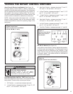
TESTING THE HEATING ELEMENT
Testing of the elements can be made with an ohmmeter
across the terminals after the connecting wires have been
removed. A cold resistance reading of approximately 10.11
ohms for the 1.15 KW heater, 14.5 ohms for the 3.3 KW
heater, 11.9 ohms for the 4.0 KW heater and 9.15 ohms for
the 5.2 KW heater should be registered.
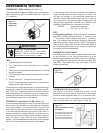
Figure 25
Heating Element
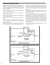
DEFROST THERMOSTAT OPERATION
HEAT PUMP WITH ELECTRIC HEAT:
YS, YM AND YL MODELS
This control is dual purpose control that acts as an outdoor
thermostat and defrost control.
When the sensing bulb, attached to the condenser coil,
senses enough icing on the outdoor coil, it will interrupt
power to the compressor and supply power to the electric
heating element until the coil temperature reaches above
43°, then the electric heater will shut off and the unit will
resume operating in the reverse cycle mode.
When the outdoor coil temperature drops below 20°, the
unit will operate in electric heat mode continuously until
the outdoor coil temperature rises above 43°.
The fan motor will not turn off when defrost occurs, and
the 4-way valve will not reverse.
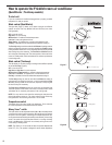
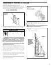
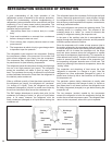
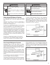
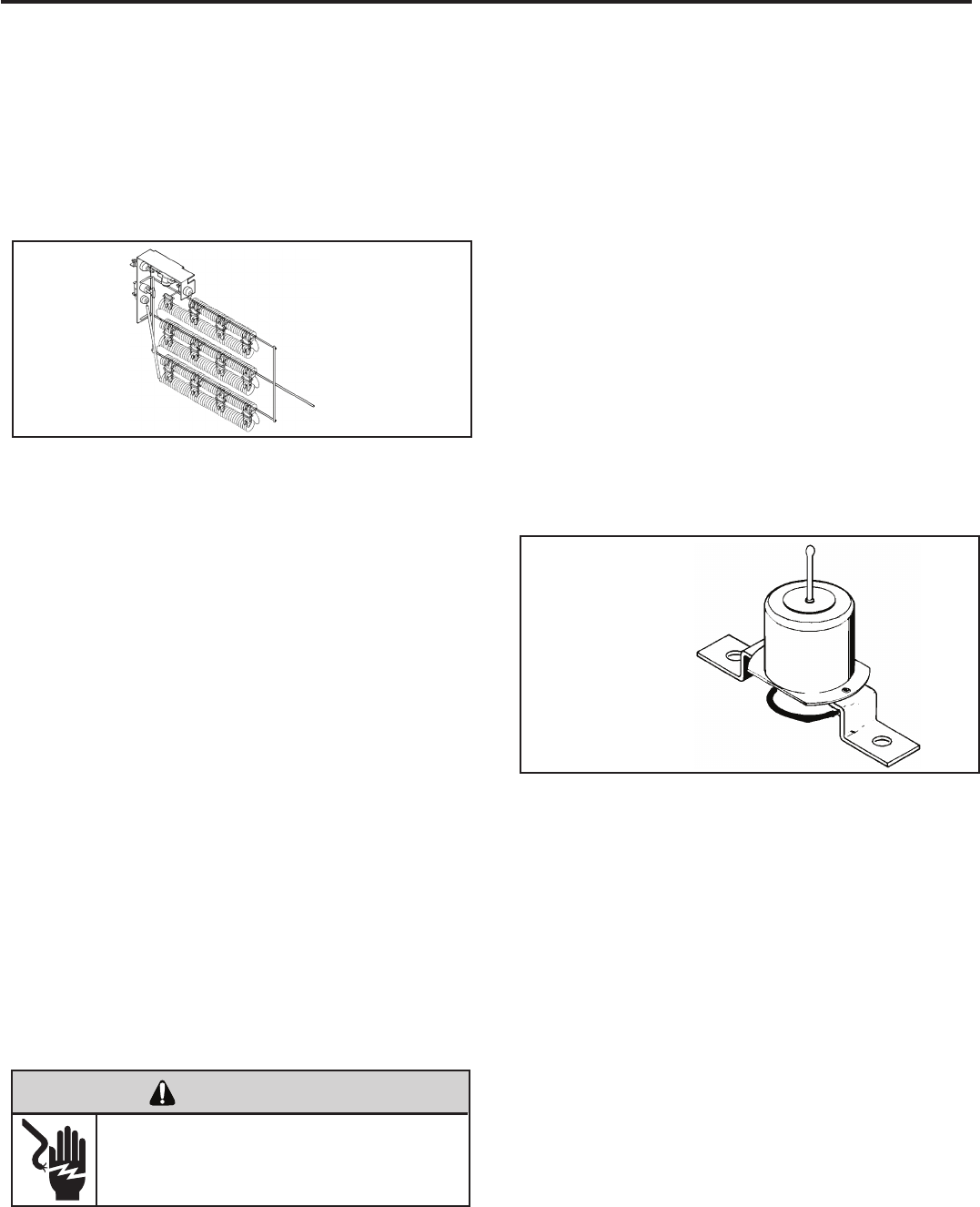
DRAIN PAN VALVE
(See Figure 26)
During the cooling mode of operation, condensate which
collects in the drain pan is picked up by the condenser fan
blade and sprayed onto the condenser coil. This assists
in cooling the refrigerant plus evaporating the water.
During the heating mode of operation, it is necessary that
water be removed to prevent it from freezing during cold
outside temperatures. This could cause the condenser
fan blade to freeze in the accumulated water and prevent
it from turning.
To provide a means of draining this water, a bellows type
drain valve is installed over a drain opening in the base
pan.
This valve is temperature sensitive and will open when
the outside temperature reaches 40°F. The valve will
close gradually as the temperature rises above 40°F to
fully close at 60°F.
Figure 26
Bellows Assembly
Drain Pan Valve
24
COMPONENTS TESTING (Continued)
ELECTRIC SHOCK HAZARD
WARNING
Disconnect power to the unit before
servicing. Failure to follow this warning
could result in serious injury or death.