


20
MECHANICAL COMPONENTS
Bellows condensate valve Temperature-sensitive valve
that opens up to drain off condensate water when the outside
temperature falls below 40°F and closes when the outside
temperature reaches 58°F.
Vent door Allows introduction of fresh air into the room
and/or exhausts stale room air outside (on select models.)
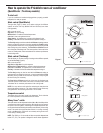
Plenum assembly Diffuser with directional louvers used
to direct the conditioned airfl ow.
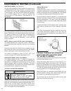
Blower wheel Attaches to the indoor side of the fan motor
shaft and is used for distributing unconditioned, room side
air though the
heat exchanger and delivering conditioned
air into the room.
Slinger fan blade Attaches to the outdoor side of the fan
motor shaft and is used to move outside air through the
condenser coil, while slinging condensate water out of the
base pan and onto the condenser coil, thus lowering the
temperature and pressures within the coil.
ELECTRICAL COMPONENTS
Thermostat Used to maintain the specifi ed room side
comfort level
System switch Used to regulate the operation of the fan
motor, the compressor or to turn the unit off. For trou
bleshoot-
ing, refer to the wiring diagrams and schematics in the back
of this service manual.
Capacitor Reduces line current and steadies the voltage
supply, while greatly improving the torque characteristics of
the fan motor and compressor motor.
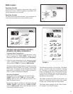
MoneySaver
Defrost thermostat (Heatpumps only)
®
switch When engaged, it sends the power
A dual purpose
supply to the fan motor through the thermostat, which allows
control that acts as an outdoor thermostat and defrost
control.
Smart Fan
Automatically adjusts the fan speed to main-
tain the desired room temp.
for a cycle-fan operation.
Fan Motor Dual-shafted fan motor operates the indoor
blower wheel and the condenser fan blade simultaneously.
Solenoid Used to energize the reversing valve on all heat
pump units.
Heating element Electric resistance heater, available in 3.3,
4.0 or 5.2 kW on select TwinTemp
®
models.
Heat anticipator Used to provide better thermostat and
room air temperature control.
HERMETIC COMPONENTS
Compressor Motorized device used to compress refrigerant
through the sealed system.
Reversing valve A four-way switching device used on all
heat pump models to change the fl ow of refrigerant to permit
heating or cooling.
Check valve A pressure-operated device used to direct the
fl ow of refrigerant to the proper capillary tube, during either
the heating or cooling cycle.
Capillary tube A cylindrical meter device used to evenly dis-
tribute the fl ow of refrigerant to the heat exchangers (coils.)
FUNCTIONAL COMPONENT DEFINITIONS
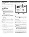
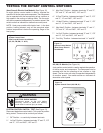
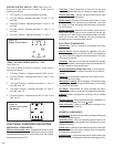
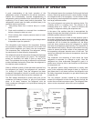
SYSTEM CONTROL SWITCH - TEST (See Figure 15)
Disconnect leads from control switch. There must be
continuity as follows:
1. “Off” Position - no continuity between terminals.
2. “Lo Cool” Position - between terminals “L1” and “C,” “LO”
and “MS.”
3. “Med Cool” Position - between terminals “L1” and “C,” “M”
and “MS.”
4. “Hi Cool” Position - between terminals “L1” and “C,” “H”
and “MS.”
5. “Fan Only” Position - between terminals “L1” and “2.”
Figure 15
System Control Switch
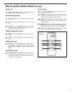
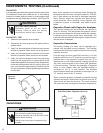
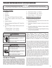
“EQ08” SYSTEM CONTROL SWITCH – TEST
(See Figure 16)
Turn knob to phase of switch to be tested. There must be
continuity as follows:
1. “Fan Only” Position – between terminals “MS” and “H”
2. “Hi Cool” Position – between terminals “L1” and “C” and
“MS” and “H”
3. “Low Cool” Position – between terminals “L1” and “C”
and “MS” and “LO”
4. “Low Heat” Position – between terminals “L2” and “2”
and “MS” and “LO”
5. “Hi Heat” Position – between terminals “L2” and “2” and
“MS” and “H”
L1
MS
2
H
LO
C
L2
B1
Figure 16
System Control Switch
(EQ Models)