


FLOATLESS LIQUID LEVEL CONTROL
The sensing elements of a fl oatless liquid level control
consists of 2 electrodes suspended in the well by
insulated wires. These wires connect to a relay which
serves as a pilot switch to the starting equipment. The
lower electode is set just above the pump, and the upper
at some distance below the static water level. The device
cuts off power to the pump automatically when the water
level drops below the lower electrode, and does not
restore power until the water level recovers to reach the
upper electrode. The Liquid Level Control can also be
used as a pilot switch in connection with elevated tanks
.
I. OPERATIONAL CHECKUP
The most reliable indication of the condition of a
submersible pump are:
(a) The current drawn by the motor
(b) The insulation resistance of the installation
below ground.
As the pump wears, the motor current increases, until
eventually the overloads trip to protect the motor. While
this automatic protection looks after an emergency
situation, proper care of a submersible installation should
include perioodic check-ups to avoid interruptions in
the water supply. Use a megger to check the insulation
resistance every six months.
Record the insulation resistance and the running current
for future reference. When the insulation resistance
fall below 10 Megohms, check it frequently for further
deterioration and pull the pump when the resistance falls
to 1/2 megohm.
When pulling the pump, either coil the cable on a reel
or raise it from the ground to dry. Check the insulation
again when the cable and splices are dry. If the insulation
value is between the line and motor casing increases
to 50 megohms or more, isolate the fault in the cable or
the splice and make the necessary repairs. However, if
the insulation reading remains low, disconnect the motor
from the cable and check the motor separately. Should
the motor be defective, check the pump end for wear and
obtain a replacement for either the motor alone, or the
pump unit, as necessary.
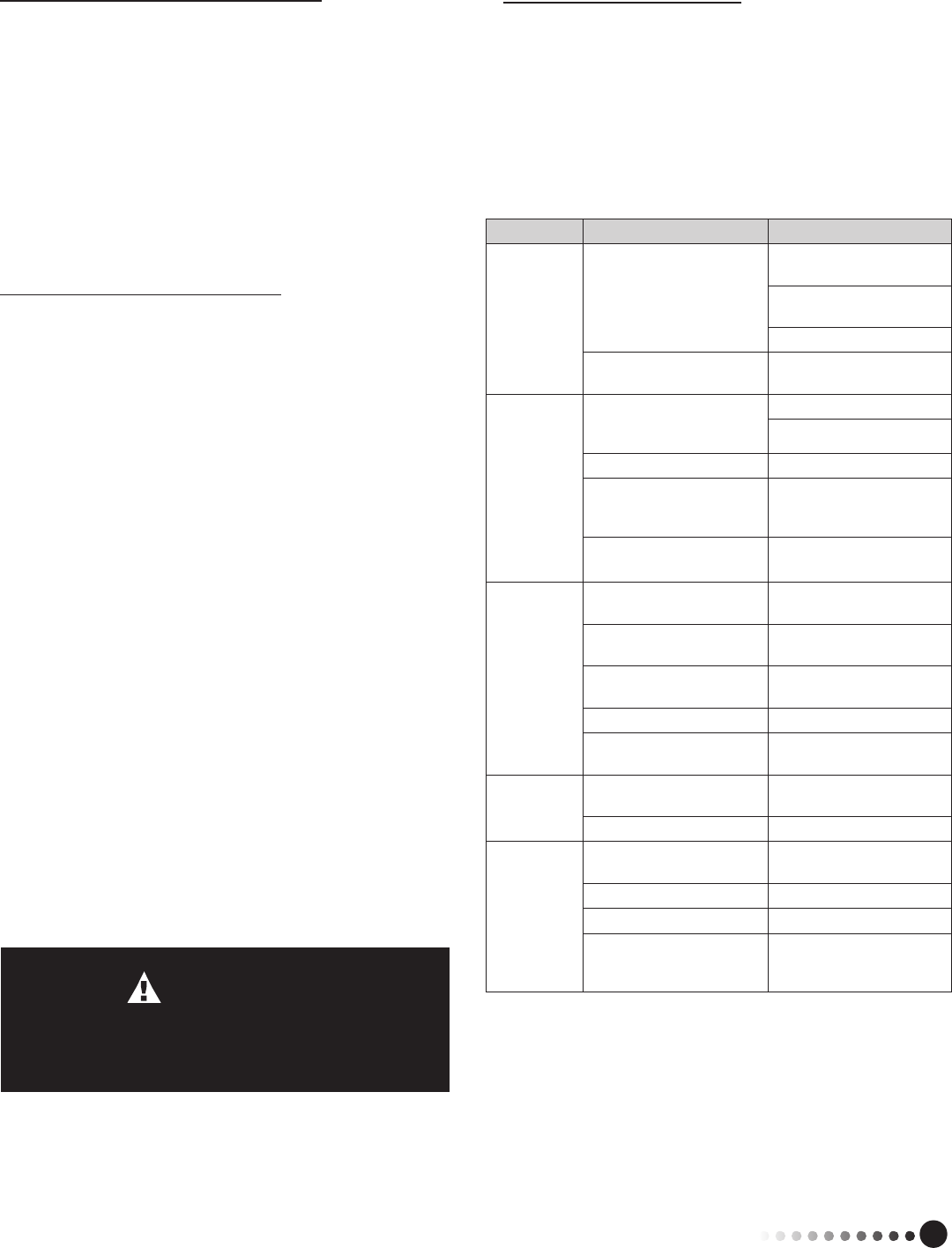
PROBLEM POSSIBLE CAUSE REMEDY
Unit fails
to start
1. Electrical trouble
Check Power source:
starter & reset
Check resistance:
cable and motor
Call Dealer or Electrician
2. Pump Sandlocked Call Dealer: pull pump
and clean
Pump fails
to deliver
water
1. Insuffi cient well yield:
water level has dropped.
Reset pump lower into well
Restrict fl ow to yield
2. Clogged intake screen Pull pump
3. Air Lock in pump Start and stop pump
several times and allow 1
min. between
4. Leak in discharge Raise pipe until leak is found.
Reduced
pump
output
1. Screen or pump partly
plugged
Pull pump and clean
2. Insuffi cient well yield Check water level: lower
pump if permissible.
3. Worn pump - excessive
wear due to abrasives.
Replace worn parts
4. Low voltage Call Electrician
5. Three Phase unit
running backward
Reverse rotation
Overload
trips
1. Worn pump or pump
bound by sand
Pull pump and clean or
replace worn parts.
2. Electrical trouble Call Dealer or Electrician
Unit cycles
too
frequently
1. Pressure switch out of
adjustment
Readjust to correct setting
or replace
2. Leaks in service line Locate and correct
3. Check valve leaking Replace
4. Water logged tank Check tank for leaks be
sure fi ttings are functioning
properly.
WARNING
HAZARDOUS VOLTAGE- CAN SHOCK, BURN,
OR EVEN KILL.
J. TROUBLESHOOTING
1. Disconnect power unless required for testing.
2. Have electrical testing done by a qualifi ed electrician.
3. Most problems occur above ground. Remove pump
only as a last resort.
When troubleshooting or servicing the pump, use all
precautions for the voltages involved.
7