C. GENERAL INFORMATION
D. SUITABILITY OF THE WELL
Submersible Pumps as well as all water pumps, are
designed to handle clean, cool, clear water. Water from
an undeveloped well often contains excessive amounts of
sand, dirt and other abrasives which can cause damage
to the pump.
Install the pump in a well which has already
been properly developed with a test pump.
The test pump also provides a means to determine
the capacity and setting of the pump to the yield
of the well. If the pump removes water at a higher
rate than the well produces, the drawdown will be
excessive and this will cause the pump to cavitate,
resulting in damge to the pump or motor.
The well must be deep enough so that the pump
suction is at least 10 ft. below the expected
drawdown level.
The insider diameter of the well casing must be large
enough to allow lowering the unit into the well without
damage to the “Power Cable”, and the splice between
the power cable and the Motor leads. Check that the
well is large enough to allow installation of the pump
at the required depth. Keep the pump atleast 5 ft.
from the bottom, particularly where there is a history
of sand in the well. Do not install the pump below the
lowest perforations in the well casing unless the well
size permits the installation of a shroud over unit to
ensure an adequate fl ow of water over the motor for
cooling purposes.
The Motor must always be immersed in fl owing water.
The Submersible pump unit comprises a vertical Turbine
pump assembly directly-coupled to a Submersible electric
motor. The connecting bracket accommodates the
coupling between the pump and motor shafts and also
serves as the water intake passage.
The pump unit is suspended in the well by the riser
pipe, and the electric power is taken down from the well
head to the motor by the Submersible cable which is
secured at intervals to the riser pipe.
Please read the manufactures separate instruction
manual for the motor, and keep it for future reference.
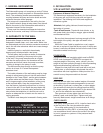
*CAUTION*
DO NOT INSTALL THE UNIT WITH THE MOTOR
RESTING ON THE BOTTOM, OR CLOSER THAN
FIVE FEET FROM THE BOTTOM OF THE WELL.
E. INSTALLATION-
SITE & SUPPORT EQUIPMENT
Equipment & Material Required;
The material and equipment necessary for the installation
of the pump will vary with the pump size and type of
installation. The following list of tools and supplies are
offered as a guide.
-Materials; Anti-galling lubricant, thread compound,
lubricating oil, grease.
-Tools & Instruments; Tripod with chain blocks, or rig
with power hoist, pipe clamps, megger, pipe wrenches,
and mechanical tools.
Be sure that the equipment is strong enough to lift the
total weight of the pump, riser pipe and water in the
riser pipes.
When the Power Cable is supplied on a reel, support
the reel on a piece of pipe laid across a pair of sturdy saw
horses. Locate the reel about six feet from the well so that
the cable unwinds from the top.
FOUNDATION
Construct a concrete foundation which must be RIGID,
LEVEL and of adequate STRENGTH to support the
complete weight of the pump, motor, column, plus the
weight of the water pumping through it without exceeding
the permissible bearing pressure for the subsoil.
Support the riser pipe at the well head with a well seal,
surface plate, or other adapter which seals the well in
accordance with local regulations. Make provision for a
conduit to carry the power cable into the well.
RISER PIPE
Make up the riser pipe from random lenghts of threaded
and coupled pipe, and make arrangements to secure it
at the well by a well seal, surface plate, or other adapter.
Use schedule 40 steel pipe for settings less than 600 ft.
For deeper settings, use schedule 40 for the bottom 600
ft., and for the remainder use schedule 80.
Take great care to keep pipes clean and free from
pebbles, scale, and thread chips. Tighten each joint
securely. Make sound, airtight connections at all fi ttings.
CHECK VALVES
If the pump setting exceeds 100 ft., install a check valve
at the fi rst joint in the riser pipe above the pump.
For a deep setting pump, a line checkvalve is
recommended for every 200 ft. of column pipe. Always
use an additional check valve at the surface if the pump
is part of a pressure system or if the pressure head
exceeds 500 ft.
3


