


ELECTRICAL INSTALLATION & TESTS
Employ a competent electrician to do the wiring in
accordance with local electrical codes. Conventional
overhead or underground installation is satisfactory for
the electrical power transmission to the Well Head.
Check that the power supply corresponds with that
shown on the name plates of the motor and control box.
NOTE; every installation requires a fused disconnect
switch or circuit breaker.
A SINGLE-PHASE unit includes a control box
incorporating overload relays, but require a magnetic
starter for automatic operation.
A THREE-PHASE unit requires a magnetic starter
with three-leg protection having QUICK-TRIP Ambient
compensated overload relays.
Note; the Warranty is void if incorrect overload relays
are used.
Mount the control equipment vertically on a post or
wall, and protect it from direct sunlight and extremes
of temperature. Make the connections to the control
equipment in accordance with the wiring diagram to avoid
damage to the motor.
Preliminary Electrical Test Pump Above Ground
After splicing the motor leads to the power cable, use a
500-volt megohm meter (megger) to test the insulation.
Connect the ground lead of the megger to the motor
frame, and the line leads to the ends of the cable
conductors. Turn the crank of the megger for 5 or 10
seconds, and check that the needle shows a value of at
least 50 megohms. Remove the megger and wet down
the motor leads and power cable with a hose or bucket.
Reconnect the megger and check the resistance again.
Should the value be appreciably less than before, it
indicates damaged insulation. Locate the damage either
by visual inspection or by checking the resistance as
each successive section of cable are immersed in water.
If the cable is new, it is probably unnecessary to check it
thoroughly from above the splice down to the motor.
*CAUTION*
TAKE GREAT CARE TO PREVENT DAMAGE TO
THE CABLE DURING INSTALLATION.
G. PUMP INSTALLATION-PERFORMANCE
Should the cable get damaged, either cut out the defective
length and splice the ends, or repair the damage, as
described in the section on cable Repair(F).
INSTALLATION
Thread the fi rst length of riser pipe into the pump
discharge and raise the pump and pipe into a vertical
position over the well. Being careful neither to drag the
pump along the ground, nor let it strike other objects
getting it into place over the well.
Lower the pump about 10 ft. into the well and fasten the
cable to the riser pipe to prevent tangling and damage.
Use electrical tape for light cable and stainless steel
bands for heavy cable.
Continue to add lengths in the same manner until the
required pump setting is reached. Secure the cable to the
riser pipe at regular intervals with tape or bands.
Use an Ohmmeter or megger to make continuity and
insulation checks on the cable at intervals of 10 to 20 ft.
as the pump is lowered. This will locate any fault in
the cable.
Where a bleeder type air charging kit is used with a
hydro pneumatic tank, install the tee and bleeder valve
before adding the last length of riser pipe. This will place
the bleeder valve about 20 ft. below the well head.
Place the sanitary well seal, surface plate. Or other
adapter on the last length of riser pipe and pass the
submersible cable through the opening provided. Then
attach the discharge tee or elbow to the riser pipe. Lower
the riser pipe to its fi nal position and tighten the well seal
or other device to support the installation in the well.
As soon as the splice joint is submerged in the water,
take a resistance reading between the power cable
conductors and ground to assure that the insulation
and the cable or the splice was not damaged during
installation process.
Initial Start-up & Performance Check
Make fi nal continuity and insulation (0 megohms or
higher) checks before connecting the cable to the control
equipment. Check that the supply voltage is within10% of
the motor rating. It is preferable for the supply voltage to
be on the high side. Check all phases of a
three-phase supply.
Check the pump and well performance before making
the fi nal connection to the discharge system.
1- Install a pressure gage and gate valve on the end of
the pipe. Close the valve.
2- Start the pump, check the pressure developed against
the closed valve. If the pressure is substantially less than
expected (don’t forget to allow for the depth to the water
level), the pump may be running backward. To change the
ratation, refer to the section “Preliminary Electrical Test
Pump Above Ground”.
3- Open the gate valve to give a low fl ow until you are
certain that the well will not yield sand. Open the gate
valve gradually to give full fl ow.
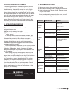
4- Use a hook-on ammeter to read the current, which
should approximate the full-load current given on the
motor nameplate, but must not exceed the service factor
rating of the motor. The service factor varies with the
make and the horsepower of the motor. Consult the
factory if insuffi cient information is given about Service
Factor performance.
5