


www.fmiproducts.com
115607-01D8
6' Max.
(15.2 cm)
6' Max.
(15.2 cm)
6' Max.
(15.2 cm)
6' Max.
(15.2 cm)
6' Max.
(15.2 cm)
6' Max.
(15.2 cm)
2" (5.1cm)
Minimum
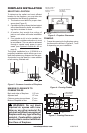
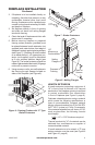
VENTING INSTALLATION
Continued
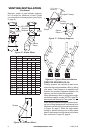
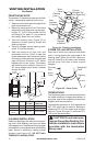
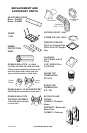
OFFSET CHART
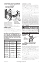
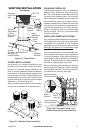
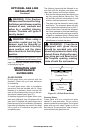
Figure 17 - Chimney Supports
Straps
A B 48" 18" 12"
4
3
/
8
" 16
3
/
8
"
ELBOW SET ONLY
9
1
/
2
" 25
1
/
4
"
1
12
1
/
2
" 30
3
/
8
"
1
14
3
/
8
" 34"
2
17
5
/
8
" 39
1
/
4
"
1 1
21
1
/
2
" 46"
1
22
3
/
4
" 48
1
/
8
"
1 2
26
3
/
8
" 54
7
/
8
"
1
26
3
/
8
" 60"
1 1
31
3
/
4
" 63
3
/
4
"
1 1
34
3
/
4
" 69"
1 1
38
5
/
8
" 75
5
/
8
"
2
39
7
/
8
" 77
7
/
8
"
1 1 1
43
3
/
4
" 84
1
/
2
"
1 1
46
3
/
4
" 87
3
/
4
"
2 1
48
7
/
8
" 93
3
/
8
"
2
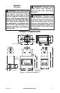
Figure 16 - Rise and Offset
B
A
Screws
2" (5.1cm)
Minimum
Angled Firestop
Ceiling
Support
Return
Elbow
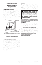
Figure 18 - Typical Offset Installations
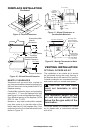
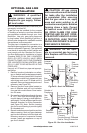
Firestop spacers are required at each point
where the chimney penetrates a oor or ceiling
joist space. Their purpose is to establish and
maintain the required clearance between the
chimney and the combustible materials.
When penetrating a oor or ceiling at an angle,
use restop spacer number 30FS-10 (see Re-
placement and Accessory Parts, page 15).
When the pipe passes through a framed open-
ing into a living space above, the restop must
be placed onto the ceiling from below as shown
in Figure 19, page 9. When the pipe passes
through a framed opening into an attic space
above, the restop must be placed on the attic
oor as shown in Figure 20, page 9.
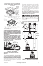
30 FT.
(9.14m)
30 FT.
(9.14m)
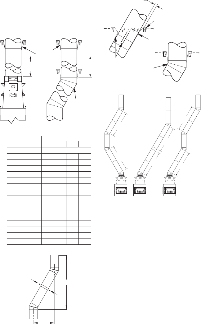
Figure 15 - Elbow Offset
Return
Elbow
12S-12DM
Support
Required
Maximum length of pipe between supports
is 6' of angle run. Maximum of two 6' angle
run sections per chimney system (see Figure
9, page 6).