


www.fmiproducts.com
115607-01D12
and connections must be tested
for leaks after the installation
is completed. After ensuring
that the gas valve is on, apply
soap and water solution to all
forming show a leak. Correct
-
-
-
ate an unvented gas log set in
removed.
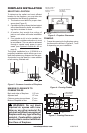
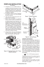
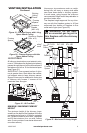
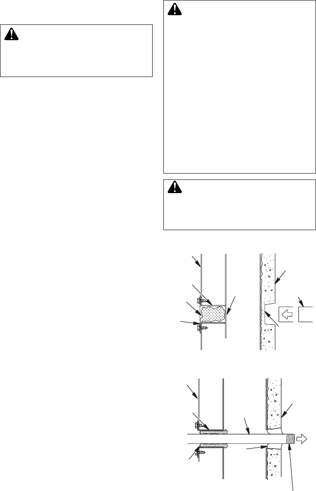
Figure 29 - Gas Line Knockout
Side
Firebrick
Finished
Side
Refractory
Knockout
Plug
Outside of
Fireplace
Gas Line
Conduit
Insulation
Gas
Conduit
Cover
1/2" Dowel
Remove
Knockout
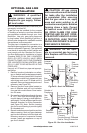
OPTIONAL GAS LINE
INSTALLATION
service person must connect
all local codes.
NOTICE: Before you proceed, make sure your
gas supply is turned off.
A gas line may be installed for the purpose
of installing a vented or vent-free decorative
gas appliance available through your local
distributor. Use only gas piping approved
by local codes. When installing a gas line, a
shutoff valve designed for installation outside
the appliance is recommended.
The gas pipe is intended for connection to a
decorative gas appliance that operates using
natural or propane/LP gas only. This appliance
must have an automatic shutoff device and
must comply with the Standard for Decora-
tive Gas Appliances for Installation in Vented
Fireplace, ANSI Z21.60. ONLY UNVENTED
GAS LOG SETS WHICH HAVE BEEN
FOUND TO COMPLY WITH THE STANDARD
FOR UNVENTED ROOM HEATERS, ANSI
Z21.11.2, ARE TO BE INSTALLED IN THIS
FIREPLACE.
Use only a 1/2" black iron pipe and appropri-
ate ttings.
1. Remove knockout indentation on refrac-
tory or rebrick wall located approximately
2" above refractory hearth oor. Knockout
indentation must be rmly tapped with any
solid object such as a 1/2" dowel until it is
released. Remove fragmented portions of
refractory (see Figure 29).
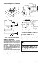
2. Remove gas line cover plate located on
rear of replace and pull out insulation
from gas line conduit sleeve. Save insula-
tion for reuse.
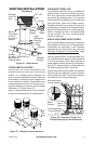
3. Run gas line into replace through the rear
at 11
1
/
4
" from oor and through gas line
conduit sleeve (if using a raised platform,
add height). Provide sufcient gas line into
replace chamber for tting connection
(see Figure 30). Note: Secure incoming
gas line to wood framing to provide rigidity
for threaded end.
4. Repack insulation around gas line and into
sleeve opening. Seal any gaps between
gas line and refractory knockout hole with
refractory cement or commercial furnace
cement, Install gas appliance or cap off
gas line if desired.
Seal
Opening
with
Refractory
Cement
Outside of
Fireplace
Gas
Line
Conduit
Repack
Insulation
Incoming
1/2" Black
Iron Pipe
Side
Firebrick
Finished
Side
Provide Enough Threaded
End for Fitting Connection
Figure 30 - Gas Line Installation