www.fmiproducts.com
115607-01D4
FIREPLACE INSTALLATION
To determine the safest and most efcient
location for the replace, you must take into
consideration the following guidelines:
1. The location must allow for proper clear-
ances (see Figure 2).
2. Consider a location where the heat output
will not be affected by drafts, air condition-
ing ducts, windows or doors.
3. A location that avoids the cutting of
joists or roof rafters will make installation
easier.
4. If an outside air kit is to be installed, ac-
cessibility to outside combustion air must
be considered. This can also be achieved
through a vented crawl space in some
cases (see Optional Outside Air Kit on
page 6).
The typical installation for a (V)PN36-A is a
projected installation which allows you to ex-
tend the replace any distance into the room.
A projection may be ideal for a new addition
on an existing, nished wall.
Back and sides of replace 1/2" min.
Adjacent wall 12" min.
Chimney outer pipe surfaces 2" min.
Bottom of replace to oor 0" min.
required air spaces with insu-
not obstruct effective opening of
material. Combustible material
must not be in contact with black
Figure 2 - Common Location of Fireplace
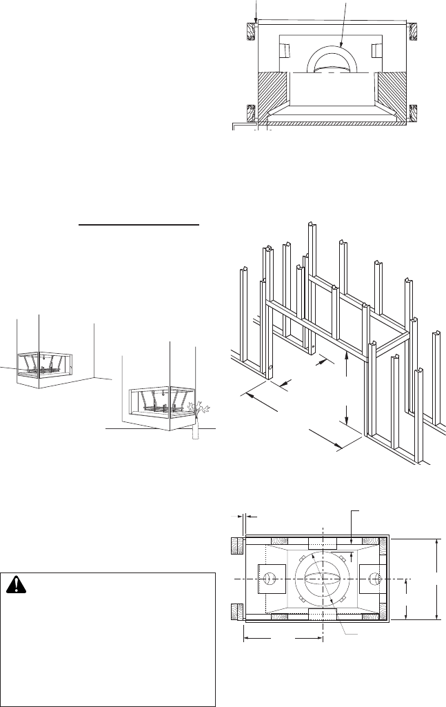
1. Frame the opening for the replace using
the dimensions shown in Figures 5, 7 and
8 depending on your installation.
39
3
/4"
(101cm)
Min.
43
1
/4"
(109.8cm)
23
5
/
8
"
(60cm)
Figure 4 - Framing Firebox
2" Min. Clearance
from Outer Pipe
to Combustibles
21
1
/
2
"
1/2" Min.
To Combustibles
11
5
/
16
"
22
5
/
8
"
Ø15 Outer Pipe
Figure 5 - Framing Clearances
Spacers on Sides of
Fireplace Provide
Required 1" (2.5cm)
Clearance
2" (5cm) Min. Clearance
From Pipe to
Combustibles
3" (7.6cm)
12" (30.4cm) Min. From Perpendicular
Side Wall to Fireplace Opening (Typ.)
Figure 3 - Fireplace Clearances


