


www.fmiproducts.com
109493-01R10
VENTING INSTALLATION
Continued
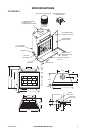
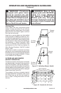
Nail Only
Outer
Perimeter
of Flashing
Storm
Collar
Flashing
Cone
Underlap
Shingles
at Bottom
Overlap
Shingles Top
and Sides Only
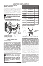
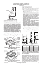
Figure 13 - Flashing Installation
When installing the ashing on a metal roof,
it is required that putty tape be used between
the ashing and the roof. The ashing must be
secured to the roof using #8 x 3/4" screws and
then sealed with roof coating to prevent leak-
age through the screw holes. A roof coating
must also be applied around the perimeter of
the ashing to provide a proper seal.
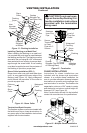
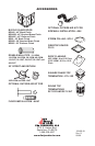
Place storm collar over pipe and slide down
until it is snug against the open edge of the
ashing (see Figure 14). Apply waterproof
caulk around the perimeter of the collar to
provide a proper seal.
Figure 14 - Storm Collar
Chimney
Pipe
Waterproof
Caulk
Storm
Collar
Flashing
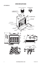
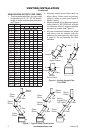
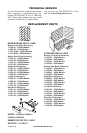
The replace system must be terminated with
the listed round top or chase terminations. In
any case, refer to the installation instructions
supplied with the termination.
Secure
Termination
to Outer
Pipe with 3
Screws
RTL-10D
Level of
Flue Gas
Outlet
Stainless
Inner Flue
Pipe
Waterproof
Caulking
Storm
Collar
Flashing
Underlap
Shingles
Figure 15 - Termination
Overlap
Shingles (Top and Sides
of Flashing Base)
-
-
low the installation instructions
provided with the termination
being used.
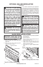
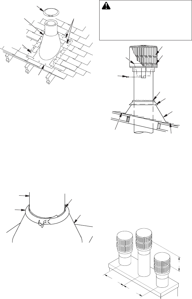
Instructions for chase installations are
included with the chase style termination
chosen. In a multiple chase installation, be
sure to provide adequate distance between
terminations to prevent smoke spillage from
one termination to another. Terminations be
separated a minimum of 24" center to center
and stacked at a minimum vertical height dif-
ference of 18" (see Figure 16).
Note: If a decorative shroud is to be installed,
contact the manufacturer for specications.
24" Min.
24" Min.
18"
Min.
Typ.
Figure 16 - Multiple Chase Installation