


www.fmiproducts.com
125078-01B6
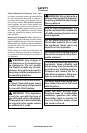
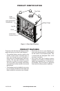
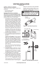
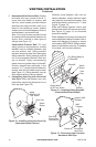
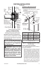
Figure 2 - Common Fireplace Locations
Flush with a wall
Through exterior wall
enclosed in a chase
Corner
installation
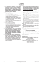
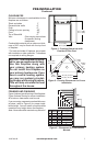
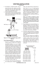
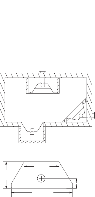
Figure 3 - Fireplace Top Dimensions
PRE-INSTALLATION
LOCATION AND SpACE
REqUIREMENTS
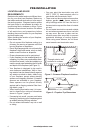
Determine the safest and most efcient loca-
tion for your direct vent replace. Make sure
that rafters and wall studs are not in the way of
the venting system. Choose a location where
the heat output is not affected by drafts, air
conditioning ducts, windows or doors. Figure
2 shows some common locations. Be aware
of all restrictions and precautions before
deciding the exact location for your replace
and termination cap.
When deciding the location of your replace,
follow these rules:
• Do not connect this replace venting to a
chimney ue serving a separate solid-fuel
burning replace or appliance.
• Due to high temperatures, do not locate this
replace in high trafc areas, windy or drafty
areas or near furniture or draperies.
• Proper clearances must be maintained.
• If your replace is to be installed directly on
carpeting, vinyl tile or any combustible mate-
rial other than wood, it must be installed on a
metal or wood panel extending the full width
and depth of the replace (see Figure 3).
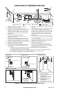
• Your replace is designed to be used in
zero clearance installations. Wall or fram-
ing material can be placed directly against
any exterior surface on back, sides or top
of your replace, except where standoff
spacers are integrally attached. If standoff
spacers are attached to your replace,
these spacers can be placed directly
against wall or framing material. See fram-
ing details, page 7.
• When locating termination cap, it is impor-
tant to observe the minimum clearances
shown in Figure 7, page 8.
• If recessing into a wall, you can avoid extra
framing by positioning your replace against
an already existing framing member.
• Do not recess termination cap into a wall
or siding.
• You may paint the termination cap with
450º F (232º C) heat-resistant paint to
coordinate with the exterior nish.
• There must not be any obstruction such as
bushes, garden sheds, fences, decks or
utility buildings within 24" from the front of
the termination cap and the front of outside
air vent.
• Do not locate termination cap and outside
air vent where excessive snow or ice build
up may occur. Be sure to clear vent ter-
mination area after snow falls to prevent
accidental blockage of venting system.
When using snow blowers, do not direct
snow towards vent termination area.
29" (36")
34
3
/
4
" (42")
21" (36")
25" (42")
41
1
/
4
" (36")
48
1
/
4
" (42")
11
7
/
8
" (36")
13
5
/
8
" (42")