


www.fmiproducts.com
125078-01B14
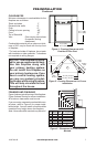
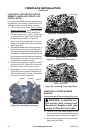
Flat Ceiling Installation
1. Cut a 11
1
/
2
" square hole in ceiling using
locating hole as a center point. Opening
should be framed to 11
1
/
2
" x 11
1
/
2
" inside
dimensions, as shown in Figure 8 on page
9 using framing lumber the same size as
ceiling joists. If area above ceiling is an
insulated ceiling or an attic, nail restop
from top side. This prevents loose insula-
tion from falling into required clearance
space. If area above ceiling is a living
space, install restop below framed hole.
Firestop should be installed with no less
than three nails per side (see Figure 15).
2. Assemble desired lengths of pipe and
elbows necessary to reach from replace
ue up through restop. Be sure all pipe
and elbow connections are fully twist-
locked (see Figure 8, page 11).
3. Cut a hole in the roof using locating hole
as a center point. (Cover any exposed
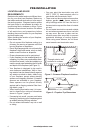
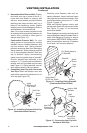
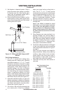
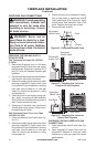
VENTING INSTALLATION
Continued
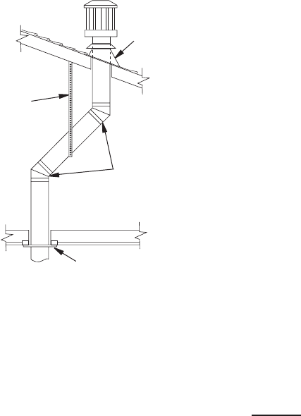
Figure 15 - Offset with Wall Strap and 45°
Elbows
45° Elbow
Wall Strap
Roof Flashing
Ceiling Firestop
open vent pipes before cutting hole in
roof.) The 11
1
/
2
" x 11
1
/
2
" hole must be
measured on the horizontal; actual length
may be larger depending on pitch of roof.
There must be a 1" clearance from vent
pipe to combustible materials. Frame
opening as shown in Figure 9, page 11.
4. Connect a section of pipe and extend up
through hole.
Note: If an offset is needed to avoid
obstructions, you must support vent pipe
every 3 feet. Use wall straps for this pur-
pose (see Figure 15). Whenever possible,
use 45° elbows instead of 90° elbows. The
45° elbow offers less restriction to the ow
of ue gases.
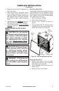
5. Place ashing over pipe section(s) ex-
tending through roof. Secure base of
ashing to roof and framing with roong
nails. Be sure roong material overlaps
top edge of ashing as shown in Figure
15. There must be a 1" clearance from
vent pipe to combustible materials.
6. Continue to add pipe sections until height
of vent cap meets the minimum building
code requirements described in Figure 7
on page 8.
Note: You must increase vent height for
steep roof pitches. Nearby trees, adjoining
rooines, steep pitched roofs and other
similar factors may cause poor draft or
down-drafting in high winds. Increasing
vent height may solve this problem.
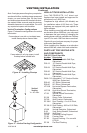
7. Twist-lock vent cap onto last section of
vent pipe.
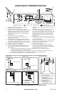
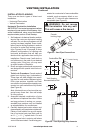
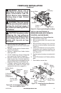
2. Set replace in desired location. Drop a
plumb line down from ceiling to position
of replace exit ue. Mark center point
where vent will penetrate ceiling. Drill a
small locating hole at this point.
3. Drop a plumb line from inside of roof to
locating hole in ceiling. Mark center point
where vent will penetrate roof. Drill a small
locating hole at this point.
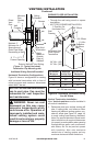
Vent Termination Chart
Minimum Height
Roof pitch Feet Min.
Flat to 6/12 1
6/12 to 7/12 1.25
Over 7/12 to 8/12 1.5
Over 8/12 to 9/12 2
Over 9/12 to 10/12 2.5
Over 10/12 to 11/12 3.25
Over 11/12 to 12/12 4
Over 12/12 to 14/12 5
Over 14/12 to 16/12 6
Over 16/12 to 18/12 7
Over 18/12 to 20/12 7.5
Over 20/12 to 21/12 8.0