


www.fmiproducts.com
105163-01E 13
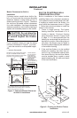
Prepare incoming black iron gas line with
Teon tape or pipe joint compound (check with
local codes as to the use of Teon tape). Com-
pounds used on threaded joints of gas piping
shall be resistant to the action of propane/LP
and should be applied lightly to ensure excess
sealant does not enter the gas line.
Complete your gas installation by connecting
the incoming gas line to the appliance regula-
tor. Secure all joints tightly with wrench but do
not overtighten. If a exible gas line is used,
take care not to kink the connector.
WARNING: All gas piping
and connections must be tested
for leaks after the installation is
completed. After ensuring that
the manual shutoff gas valve is
open, apply a soap and water
solution to all connections and
joints. If bubbles appear, leaks
can be detected and corrected.
DO NOT USE OPEN FLAME FOR
LEAK TESTING AND DO NOT
OPERATE ANY APPLIANCE IF
A LEAK IS DETECTED.
INSTALLATION
Continued
GAS SUPPLY TESTING
Note: This section is intended as a guide for
qualied technicians installing gas to this
vent-free rebox.
CAUTION: Do not connect
vent-free heater before pressure
testing gas piping. Damage to
gas valve may result and an un-
safe condition may be caused.
The appliance and its’ individual shutoff valve
must be disconnected from the gas supply
piping system during any pressure testing of
that system at test pressures in excess of 1/2
psig (3.5 kPa).
The appliance must be isolated from the gas
supply piping system by closing manual shut-
off valve during any pressure testing of the gas
supply piping system at test pressures equal
to or less than 1/2 psig (3.5 kPa).
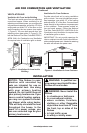
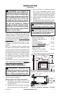
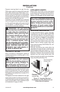
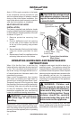
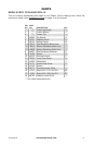
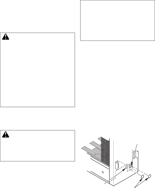
Figure 15 - Locating Electrical
Connection and Gas Connection on
Either Side of Fireplace
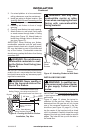
HARD-WIRING FIREBOX
Model FBPS and FGPN can be hard-wired
to the duplex outlet located inside the rebox
bottom if desired. This allows the blower ac-
cessory to be plugged into the duplex outlet.
NOTICE: A qualied electrician
must connect electrical wiring to
duplex outlet for built-in instal-
lation. Follow all local codes. In
absence of local codes follow
The National Electric Code ANS/
NFPA 70.
ELECTRICAL INSTALLATION
A model GA3500A blower system assembly
is available for use with the FBPS and FGPN
(-LS) vent-free rebox as an optional acces-
sory. This blower is designed to be installed
on either side of the FBPS and FGPN(-LS)
rebox, when provisions for a 120 VAC sup-
ply connection are made at either end of the
cabinet. Use of a blower system other than
those manufactured by FMI PRODUCTS, LLC
voids the warranty.
Electrical connections are made within the
receptacle with wires that are routed through
the bushing provided (see Figure 15). The re-
ceptacle may be relocated to either side, when
necessary. However, the cover plate must be
replaced over the unused access point. Be
certain to properly ground the vent-free rebox
using the green grounding wire.
Cover
Plates
Electrical
Connection
Access Hole
Gas Connection
Access Hole