


www.fmiproducts.com
105163-01E10
INSTALLATION
Continued
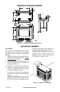
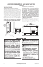
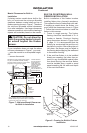
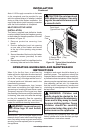
Mantel Clearances for Built-In
Installation
If placing custom mantel above built-in re-
box, you must meet the minimum allowable
clearance between mantel shelf and top of
rebox opening shown in Figure 7. These are
the minimum allowable mantel clearances
for a safe installation. Use larger clearances
wherever possible to minimize the heating of
objects and materials placed on the mantel.
CAUTION: Do not allow the
vent-free gas log heater to touch
or extend beyond the rebox
screen.
If your installation does not meet the above
minimum clearances in Figure 7, you must:
• raise the mantel to an acceptable height,
OR
• remove the mantel.
Supplied
Firebox
Hoods Must
Be Used at
All Times
Wire-mesh
Screen
Firebox Top
Mantel
Shelf
3"
6"
9
1
/
4
"
Combustible
Material 1
1
/
2
"
Max Thickness
Note: All vertical
measurements are
minimum distances
from top of fireplace
hood to bottom of
mantel shelf. These
minimum clearances
replace any other
recommended
clearances supplied
with your ANS Z21.1 1.2
approved gas logs.
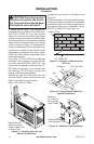
Wall board or facing material (above firebox)
may be of combustible material, including
decorative mantel ornaments or other similar
projections off of the facing material.
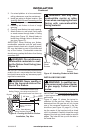
Top Frame
(Combustible Material)
12" 15" 18"
7" Min.
Note: Fireplace shown as cross-section for clarity .
Mantel material may not be less than 7" from top of
hood. Do not cover louver openings.
BUILT-IN OR INTERNAL WALL
FIREBOX INSTALLATION
Built-in installation of this rebox involves
installing rebox into a framed-in enclosure.
This makes the front of rebox ush with wall.
If installing a mantel above the rebox, you
must follow the clearances shown in Figure
7. Follow the instructions below to install the
rebox in this manner.
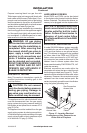
1. Frame in rough opening. The firebox
framing should be constructed of 2 x 4
lumber or heavier. Construct framing
using dimensions shown in Figure 8 and
9, page 11. It is recommended that the
framing be constructed rst and the unit
be placed in position. After sliding the unit
into place, the anges may be nailed to
the framing before applying the wallboard
to the exterior framing.
2. If the vent-free rebox is to be installed
directly on carpeting, tile (other than ce-
ramic) or any combustible material other
than wood ooring; the vent-free rebox
must be installed upon a metal or wood
panel extending the full width and depth
of the vent-free rebox.
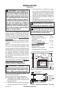
Figure 7 - Minimum Mantel Clearances
for Built-In Installation
4" Min.
43
3
/
4
" Min.
36" Min. to
Facing Wall
22
3
/
4
"
Min.
Facing
Wa ll
Wa llboard
Gas Line
Facing Wall
(Base line)
Board
Base
40
1
/
4
" Min.
Figure 8 - Framing for Built-In Firebox
Installation