


www.fmiproducts.com
119315-01D 17
INSTALLATION
Continued
WARNING: Read and fol-
WARNING: Do not connect
this thermostat to any electrical
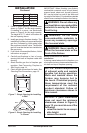
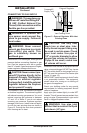
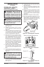
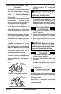
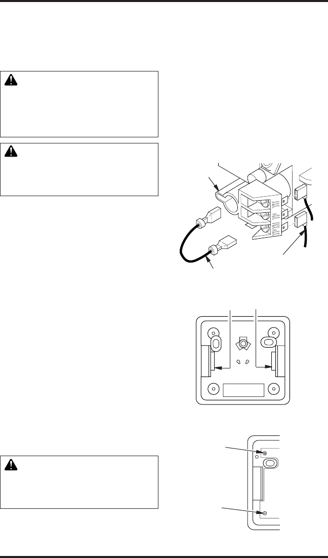
1. Disconnect jumper wire from control valve
(see Figure 19).
2. Connect one terminal of 25 ft. wire to
“TPTH” terminal on control valve (see
Figure 19).
3. Connect remaining wire terminal to the
“TH” terminal on the control valve. Make
sure that wire terminals are in the positions
on your unit as pictured in Figure 19.
4. Route the 25 ft. wire to a convenient loca-
tion to mount your thermostat (no outside
wall). IMPORTANT: The wire may be
shortened but must not be lengthened.
The thermostat should be mounted 54"
above the oor in a location where there
is good air circulation. Avoid heat sources
such as lamps, direct sunlight, replace
or heat and air conditioning ducts.
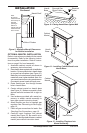
5. Gently remove the cover of the thermostat
from the base. Grasp the sides of the
cover rmly and pull to separate from the
base.
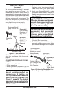
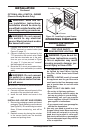
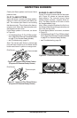
6. Feed the electrical wires through the rect-
angular slots on each side of the base (see
Figure 20).
WARNING: Do not con-
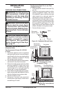
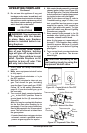
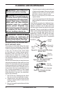
7. Connect one bare wire end to each termi-
nal (“W” and “R”) of the thermostat base
(see Figure 21).
Figure 19 - Connecting Wire Terminals
One terminal
of 25 ft. wire
Control
Valve
Jumper Wire
8. Install the base onto the wall with the
provided screws.
9. Move the temperature adjustment back
and forth to insure the bimetal is free from
restrictions.
10. Replace the cover onto the base. (Upon
installation, the thermostat must be al-
lowed to stabilize at room temperature
for a minimum of 30 minutes for proper
operation).
11. Set switch on replace to Auto position.
12. Set the temperature adjustment to the
desired setting. This thermostat has been
electronically calibrated at the factory. No
adjustment or leveling is necessary.
Figure 20 - Back View of Thermostat
Base
Feed wires through rectangular slots
W
R
Figure 21 - Thermostat Base Terminals
“W” and “R”
Terminal “W”
Terminal “R”