10 Calibration Procedure
Sometimes the user may want to calibrate the dry-well to improve the tempera
-
ture set-point accuracy. Calibration is done by adjusting the controller probe
calibration constants R0 , ALPHA, and DELTA so that the temperature of the
dry-well as measured with a standard thermometer agrees more closely with the
set-point. The thermometer used must be able to measure the well temperature
with higher accuracy than the desired accuracy of the dry-well. By using a
good thermometer and following this procedure the dry-well can be calibrated
to an accuracy of better than 0.5°C over its full range.
10.1 Calibration Points
In calibrating the dry-well, R0, ALPHA, and DELTA are adjusted to minimize
the set-point error at each of three different dry-well temperatures. Any three
reasonably separated temperatures may be used for the calibration. Improved
results can be obtained for shorter ranges when using temperatures that are just
within the most useful operating range of the dry-well. The farther apart the
calibration temperatures, the larger will be the calibrated temperature range but
the calibration error will also be greater over the range. If for instance 150°C to
350°C is chosen as the calibration range then the calibrator may achieve an ac-
curacy of say ±0.3°C over the range 150 to 350°C. Choosing a range of 200°C
to 300°C may allow the calibrator to have a better accuracy of maybe ±0.2°C
over the range 175 to 325°C but outside that range the accuracy may be only
±0.5°C.
10.2 Calibration Procedure
1. Choose three set points to use in the calibration of the R0, ALPHA, and
DELTA parameters. These set points are generally 50.0°C, 200°C, and 350.0°C
but other set points may be used if desired or necessary.
2. Set the dry-well to the low set-point. When the dry-well reaches the
set-point and the display is stable, wait 15 minutes or so and then take a reading
from the thermometer. Sample the set-point resistance by holding down the
SET key and pressing the DOWN key. Write these values down as T
1
and R
1
respectively.
3. Repeat step 2 for the other two set points recording them as T
2
and R
2
and T
3
and R
3
respectively.
4. Using the recorded data, calculate new values for the R
0
, ALPHA, and
DELTA parameters using the equations given below:
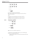
10.2.1 Compute DELTA:
ATT=−
32
BTT=−
21
43
10 Calibration Procedure
Calibration Points


