


5 Parts and Controls
The user should become familiar with the dry-well calibrator and its parts:
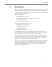
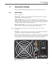
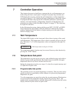
5.1 Rear Panel
Figure 1 on page 13.
Power Cord - At the rear of the calibrator is the removable power cord inlet
that plugs into an IEC grounded socket.
Power Switch - The power switch is located on the power entry module
(PEM). The PEM also houses the fuses and the dual voltage selector. The PEM
and Heater Voltage Switch (see below) allow the unit to be field switchable for
115 VAC (±10%) or 230 VAC (±10%) operation.
Heater Voltage Switch - To be used only when changing the input voltage.
(See Section 6.3 for instructions on changing the input voltage.)
Note: The input voltage and heater voltage switch settings should always be the
same value.
Serial Port - A DB-9 male connector is present for interfacing the calibrator to
a computer or terminal with serial RS-232 communications.
Fan - The fan inside the calibrator runs continuously when the unit is being op-
erated to provide cooling for the instrument. It has two speeds, a slow speed for
control operation and a faster speed for rapid cooling. Slots at the top and
13
5 Parts and Controls
Rear Panel
Figure 1 9140 Back Panel