6 General Operation
6.1 Calibrator Set-Up
Place the calibrator on a flat surface with at least 6 inches of free space around
the instrument. Overhead clearance is required. DO NOT place under a cabinet
or other structure.Plug the power cord into a grounded mains outlet. Observe
that the nominal voltage corresponds to that indicated on the back of the
calibrator.
Gently insert the probe sleeve into the well. The probe sleeve should be of the
smallest hole size possible while allowing the probe to slide in and out easily.
Sleeves of various sizes are available from the manufacturer. The well must be
clear of any foreign objects, dirt and grit before the sleeve is inserted. The
sleeve is inserted with the two small tong holes positioned upward.
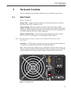
Turn on the power to the calibrator by toggling the switch at the rear of the in
-
strument to the “l” (on) position. The fan will begin circulating air through the
instrument. After a brief self test the controller should begin normal operation
showing the well temperature. The block will heat or cool until it reaches the
programmed set-point.
6.2 Changing Display Units
The 9140 can display temperature in Celsius or Fahrenheit. The temperature
units are shipped from the factory set to Celsius. To change to Fahrenheit or
back to Celsius there are two ways:
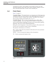
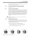
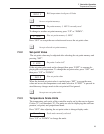
1 - Press the “SET” and “UP” simultaneously. This will change display units.
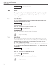
2 - Press the “SET” key three times from the temperature display to show
Un= C
Press the “UP” or “DOWN” key to change units.
6.3 Switching to 230 V Operation
The 9140 is switchable from 115 VAC to 230 VAC 50/60 Hz. Switching the
voltage can change the calibration, so it is recommended to recalibrate the unit
after changing the input voltage.
To change from 115 VAC to 230 VAC:
•
Unplug the unit
•
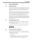
With a small straight slot screwdriver remove the fuse holder located on
the rear panel. Replace the two 6 amps fuses with 3 amp 250 V fuses.
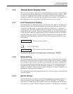
•
Replace the fuse holder with the “230V” in the display window.
17
6 General Operation
Calibrator Set-Up


