


The sensor connectors are provided on the rear panel of the furnace for con
-
necting the control and cutout thermocouples. They are Type K miniature con
-
nectors and allow for ease of system assembly and sensor replacement.
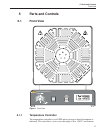
5.3 Back View
See Figure 3.
5.3.1 The Power Cable
The furnace is provided with a 12 gauge two conductor with ground power ca
-
ble. The user must provide a connector to meet the needs of the installation. Be
sure to follow electrical codes. A separate permanent earth ground is provided
with this instrument. This is required to be installed correctly for safe operation
of the instrument.
5.3.2 Nomenclature
The nomenclature on the rear of the furnace provides information to the user in
case service is required. The nomenclature includes the manufacturer, manufac-
turer location, model number, and serial number specific to this unit. Refer to
the model number and serial number whenever service is required.
5.3.3 Fuses
Two 20 A F 250 V fuses are used to protect the system, one for each leg of the
230 VAC power. The fuses are located inside the control cabinet. If the furnace
fails to operate, check the fuses first.
Two 1 A F 250 V fuses are located inside the control cabinet for the controller.
21
5 Parts and Controls
Back View