


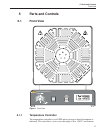

two LED type displays. The upper display normally indicates the actual tem
-
perature while the lower display indicates the set temperature. The displays are
also utilized in setup and alarm functions. Other indicators include the OP1 and
OP2 indicator lights. The OP1 indicator lights when the heater is on. The OP2
is not functional on the unit. The “R” indicator lights during programmed
ramping. The “M” indicator flashes if the sensor fails. If the sensor opens, the
heaters shut off.
The up and down Temperature Adjustment arrow keys are the only temperature
controls normally used. A quick single stroke increments or decrements the
temperature setting. Holding the buttons down causes a gradual acceleration of
the temperature setting. These same buttons are used to adjust other parameters
in conjunction with the “PAR” button.
Further information about the controller operation can be obtained from the
temperature controller installation and operation manual included with the
instrument.
5.1.2 Over Temperature Cutout
The over temperature cutout is located at the left side of the control panel. The
controls include a temperature limit adjustment control knob calibrated in Cel-
sius and “limit exceeded” indicator light. The cutout is adjustable by the user
within the temperature range of the furnace with divisions shown every 25°C.
The indicator light turns on when the set limit is reached. The cutout can be set
to Manual Reset or Auto Reset. The button on front panel allows the user to re-
set the cutout. The unit leaves the factory with the unit set in the Manual Reset
Mode. In the Auto Reset Mode, the temperature resets when it has dropped
about 20 degrees.
The cutout is provided to allow the user to set the maximum furnace tempera-
ture to a point within the safe range of the sensor(s) being calibrated and to pro
-
tect the furnace from exceeding its own safe operating range. Limiting the top
end also helps extend the life of the heaters.
The cutout controls a relay which is wired in series with the heater circuit. The
cutout is provided as a safety backup in case the solid state relay driven by the
temperature controller fails (shorts) causing thermal runaway.
5.1.3 Power and Heater Switches
The power switch is located just left of the temperature controller. The top is
pressed inward to turn the unit on.
Note: The internal fans are wired ahead of the switch so they stay on until
the unit is cooled even though the main power may have been turned off.
This way the outer surfaces of the enclosure are not heated to dangerous
levels from stored heat.
9112A Calibration Furnace
User’s Guide
18