MR850 Technical Manual * Revision J * Issued November 2005 * Ref. 185041340 (185041713 internal)
40
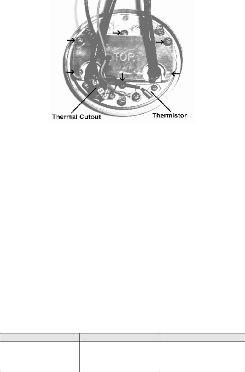
Figure 7.7 Showing location of Heater Plate Thermistor
Thermal Cutout and Element Screws
8. Solder the wires from the new harness to the heater plate thermal cutout.
9. Attach the cable ties provided to the heater plate harness.
10. Place heater plate back into position, ensuring the springs underneath the heater plate are
in place. Attach to the humidifier's case using the three long screws that were previously
removed.
11. Connect the heater plate element, thermistor and thermal cutout harnesses to the power
PCB.
12. Close the case (section 7.2.8).
Checking the heater plate element
1. Open the case (section 7.2.1).
2. Disconnect the heater plate element, thermistor and thermal cutout harnesses from the
power PCB.
3. Measure the resistance between the 2 contacts on the heater plate element connector (this
is the large three pin connector).
The resistance of the heater plate element should measure the same as outlined in the table
below:
MR850 Model Number Supply Voltage Heater Plate Resistance
MR850Axx
MR850Pxx
MR850Jxx
MR850Gxx
230 V~
127 V~
115 V~
100 V~
353 ± 12 Ohms
108 ± 3 Ohms
88 ± 3 Ohms
67 ± 2 Ohms
If the measured resistance is outside this range, replace the heater plate element (steps 4 to 9).
If the heater plate element is within specification, go to step 10.
NOTE: If the heater plate element requires replacing, a heater plate element service kit is
required - see Section 10. Spare Parts.
4. Remove the two visible screws holding the heater plate element reflector. Remove the
shield, making sure the washers are not lost. Unscrew the last four screws on the element
cover (Figure 7.7).


