MR850 Technical Manual * Revision J * Issued November 2005 * Ref. 185041340 (185041713 internal)
39
3. If the thermal cutout "clicks" when pushed, it has been previously activated, and is now
reset. NOTE: If the heater plate is still hot, it must be allowed to cool sufficiently before the
thermal cutout will reset.
4. Close the case (section 7.2.8).
Replacing the heater plate thermistor
NOTE: A Heater plate thermistor service kit is required. (Part Number: 043 041 254)
1. Open the case (section 7.2.1).
2. Disconnect the heater plate element, thermistor and thermal cutout harnesses attached to
the power PCB.
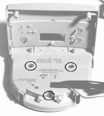
3. Remove the three screws holding the heater plate - see Figure 7.6.
4. Cut cable ties attached to the heater plate harnesses.
Figure 7.6 Showing location of Heater Plate screws
5. Remove screw holding heater plate thermistor - see Figure 7.7.
6. Unsolder the wires attached to the thermal cutout, and remove the old thermistor and
harness.
7. Place the new thermistor into position, and attach using the screw.


