


9500 Valve
Instruction Manual
Form 2433
November 2007
9
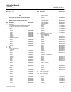
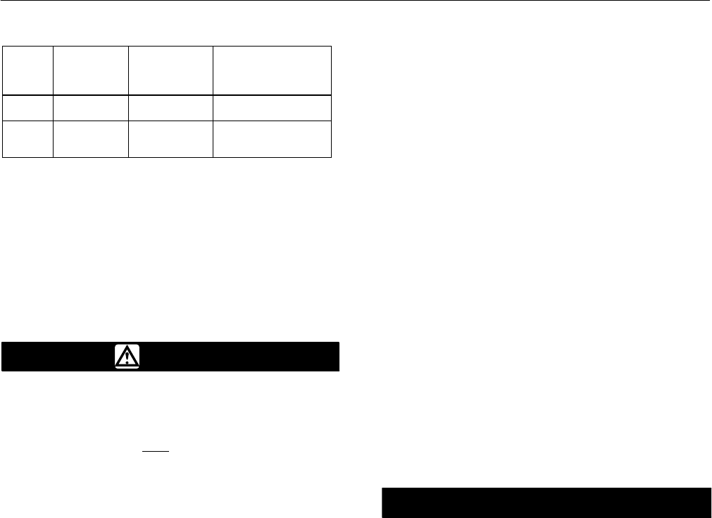
Table 5. Taper Pin Details for 9500 Series Valves
VALVE
SIZE,
NPS
SHAFT
DIAMETER
mm (Inches)
AMERICAN
STANDARD
TAPER
PIN SIZE
DRILL SIZE
2
3, 4
12.7 (1/2)
15.9 (5/8)
2
3
#20 (0.161 Inches)
#16 (0.177 Inches)
6
8, 10
12
19.1 (3/4)
25.4 (1)
31.8 (1-1/4)
4
6
7
13/64 Inches
9/32 Inches
21/64 Inches
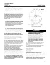
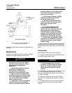
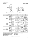
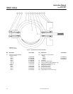
Reassembly
Before reassembling the valve, clean and inspect all
parts. Key number locations are shown if figure 7.
Refer to the Parts List section to obtain replacement
parts.
WARNING
Do not lubricate parts when used in
oxygen service, or where the
lubrication is incompatible with the
process media. Any
use of lubricant
can lead to the sudden explosion of
media due to the oil/oxygen mixture,
causing personal injury or property
damage.
1. Insert the liner (key 2) into the valve body. A
small amount of silicone grease applied to the
outside surface of the liner will aid insertion of the
liner. However, do not use grease if the valve is to
be used for oxygen service.
In vacuum service applications, upon customer
request, you may use Eccobondr 285/24LV bonding
agent (Fisherr part no. G1414006992) to bond the
liner to the valve. Though bonding is not required
use the lettered steps below when bonding the liner
to the valve body. If a different agent is to be used,
follow instructions furnished by the bonding agent
manufacturer. In absence of instructions, consult
your Emerson Process Management sales office.
a. Roughen bonding surface of liner with a stiff
wire brush. De-grease bonding surfaces of the
liner and valve body with solvent.
b. Mix the two epoxy components thoroughly and
spread a thin coat [approximately 0.38 mm (0.015
inches) thick] of the mixture over all bonding
surfaces of the valve body and liner.
c. Insert the liner into the valve body. Align the
liner shaft holes with valve body shaft holes.
Remove excess bonding agent from shaft holes
and exposed liner surfaces.
d. Insert the disc (key 3), thrust sleeve
assemblies (key 6), and shaft (key 4) into the
valve body. Be sure the thrust sleeve assemblies
engage the liner recesses to ensure proper liner
positioning. Rotate the disc to the closed position.
e. Lay the valve on one valve face and add
weights to the other face to ensure a tight bond.
Allow to cure for 24 hours. Then, proceed with
the following reassembly steps.
2. Insert the thrust sleeve assemblies into the valve
body. Be sure that the thrust sleeve assemblies
enter the liner recesses to align the shaft holes, by
temporarily inserting the shaft(s) (key 4).
3. A new disc and shaft should be installed if the
taper pin holes have been widened by loosening of
the taper pins (key 15).
Omit the following steps 4 through 8 if a new disc
and shaft assembly is to be installed or if the old disc
and shaft are to be reused. Use new taper pins
whenever the disc has been removed.
CAUTION
If a new disc is required, a complete
disc/shaft assembly must be
purchased to avoid damage to valve
parts. The old valve shaft cannot be
used with a new disc.
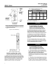
If a new shaft (without disc) has been purchased, be
sure to mark the shaft to indicate the disc position as
shown in figure 2.
4. Making certain the taper pin holes are on the
actuator side of the valve body, insert the disc into
the valve body. Position the disc at the fully closed
position.
5. Installing splined shaft:
a. If the old shaft is available, insert it into the
valve body and disc. Line up the taper pin holes
in the disc and shaft; measure and record the
distance between the valve body and the splined
end of the shaft. Remove the old shaft and insert
the new, un-drilled shaft. Position the shaft so
that there is the same distance between the valve
body and the end of the shaft as noted above.