


9500 Valve
Instruction Manual
Form 2433
November 2007
5
result if the partial O-ring faces are not properly
supported. Do not use flanges having an inside
diameter larger than the maximum shown in
table 3.
The NPS 6 to 10 sizes must not be used with slip-on
flanges unless flange adaptors are used to support the
liner. When using slip-on flanges with other sizes, be
certain the valve is carefully centered to ensure that
the partial O-ring faces are in full contact with the
adjacent flanges.
c. When a flange adapter is necessary, a flange
gasket must be installed between the line flange
and the flange adapter. Do not use a flange
gasket between the valve and the flange adapter.
Additional gasketing material at this location
could damage the liner.
d. The valve disc must be in the closed position
when the valve is being inserted into the pipeline.
If the valve disc is not closed, it could be
damaged against the mating piping or flanges.
6. Insert the valve into the pipeline. Insert four
flange studs or bolts through the flanges to support
the valve.
7. Center the valve carefully on the flanges by
measuring equal distances at the top and bottom
and equal distances at the sides.
8. Insert the remaining flange studs or bolts. Tighten
the studs or bolts evenly. Normal flange bolt torques
may be used because liner compression is limited by
metal-to-metal contact between flanges and the
valve body.
9. Rotate the valve disc manually to be certain the
disc clears the adjacent piping or flanges as it
opens. If necessary, disconnect the power
actuator-valve linkage, but do not disturb the
adjustment of the turnbuckle or adjustable linkage. If
the disc hits the flange, loosen flange bolting
temporarily while re-centering the valve. If the
problem cannot be corrected in this manner, it will be
necessary to use line flanges with larger inside
diameters adjacent to the valve.
10. For hazardous atmosphere or oxygen service
valves, read the following Warning, and provide the
following bonding strap assembly if the valve is used
in an explosive atmosphere.
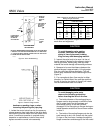
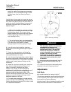
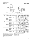
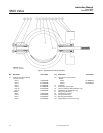
Figure 4. Grounding Assembly
37A6528-A/DOC
WARNING
The valve drive shaft is not necessarily
grounded to the pipeline when
installed. Personal injury or property
damage could result, if the process
fluid or the atmosphere around the
valve is flammable, from an explosion
caused by a discharge of static
electricity from the valve components.
If the valve is installed in a hazardous
area, electrically bond the drive shaft
to the valve.
11. Attach the bonding strap assembly (key 131,
figure 4) to the shaft with the clamp (key 130,
figure 4).
12. Connect the other end of the bonding strap
assembly to the valve flange cap screws.
Adjustments
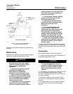
Hub Seals
Key number locations are shown in figure 7.
Thrust sleeve assemblies (key 6) seal the disc hubs.
In time, especially with frequent valve disc rotation,
these seals may require adjustment.
Adjust the seals if there is leakage through the valve
body around the valve shaft. A small amount of