


9500 Valve
Instruction Manual
Form 2433
November 2007
4
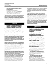
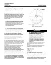
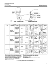
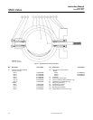
Figure 2. Valve Shaft Marking
A2755-1/IL
LOCATION OF
INDEX MARK
ON END OF
VALVE SHAFT
TAIL OF
Fishtail
DISC
LOCATION OF
FLAT SPOT
ON VALVE
SHAFT
NOSE OR
LEADING
EDGE OF
DISC
OPEN
FLOW
WITH SPLINED
VALVE SHAFT
EQUAL MEASUREMENTS BETWEEN VALVE FACE AND DISC
EDGE AT TOP AND BOTTOM ENSURE FULLY CLOSED DISC.
FOR Fishtail DISC, PARTIAL KEYWAY OR FLAT SPOT IS ON
SAME SIDE AS NOSE OF DISC.
1
1
2
1
2
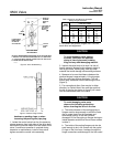
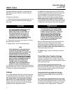
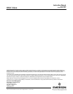
Figure 3. Partial O-Ring Location
A6017/IL
hardware or packing rings, or when
loosening the packing box pipe plug.
1. Isolate the control valve from the line pressure,
release pressure from both sides of the valve body,
and drain the process media from both sides of the
valve. If continuous operation is required during
inspection or maintenance, install a three-valve
bypass around the control valve assembly.
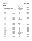
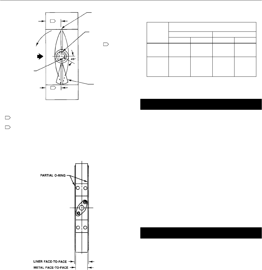
Table 3. Maximum and Minimum Allowable
Mating Flange Diameters
VALVE
MAXIMUM AND MINIMUM DIAMETER OF MATING
PIPING OR FLANGES
VALVE
SIZE, NPS
Minimum Maximum
SIZE,
NPS
mm Inches mm Inches
2
3
4
30
64
89
1.20
2.50
3.50
64
92
117
2.50
3.62
4.62
6
8
10
12
145
196
246
297
5.70
7.70
9.70
11.70
171
222
273
330
6.75
8.75
10.75
13.00
2. Be certain the pipeline flanges are in line with
each other and supported.
CAUTION
To avoid damaging valve seating
surfaces, make sure the adjacent
piping is free of pipe scale, welding
slag, and any other damaging material.
3. Inspect the valve body to be sure it is free of
foreign material. Make sure the adjacent piping is
free of pipe scale, welding slag, and any other
material that could damage valve seating surfaces.
4. Measure to be sure the distance between the
pipeline flanges is approximately 1/4 inch greater
than the valve face-to-face dimension. This will
ensure easy installation without distorting the liner
(figure 3).
5. For conventional discs, flow may be in either
direction; for Fishtail discs, flow must be such that
the tail of the disc (as shown in figure 2) will rotate
into the downstream side of the valve.
CAUTION
To avoid damaging valve parts,
observe the following precautions
before inserting the valve in the line.
a. The inside diameter of the mating piping or
flanges must be large enough to allow the valve
disc to rotate freely into the upstream and
downstream piping, or the disc could be
damaged. Do not use piping or flanges having an
inside diameter smaller than the minimum shown
in table 3.
b. The inside of the mating flange must also be
small enough to be in full contact with the partial
O-rings on the liner faces. Leakage through the
flange connections and damage to the liner could