


Page 2
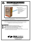
Figure 1
I. GENERAL INFORMATION
This product is not sold as a medical device and is not for the purpose of diagnosis of any disease or condition nor for
use in the mitigation, treatment, or prevention of any disease or condition.
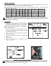
There are different size units available, depending on the square footage of your home. See chart below for
determining your homes needs.
Lamp Length
Minimum
Duct
Width
Volts Amps
Hz
Watts
Max Air
Temp
°F
Lamp Intensity at 1
meter
Recommended
Max Sq. Feet
12” 9 120/240 0.5 60 30 150°
37 μW/cm
2
1500
18” 14 120/240 0.5 60 30 150°
73 μW/cm
2
2000
28” 22 120/240 1.1 60 60 150°
105 μW/cm
2
3000
WARNING: Before installing or servicing a humidifier, air filter, heat system, or this unit, etc., always turn all power
OFF and have units unplugged. Electrical shock can cause personal injury or death. Never expose eyes or skin to
direct UVC light from any source.
II. INSTALLATION
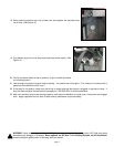
1. Determine a suitable location on either the supply or
return for the unit as shown in Figure 1. The unit must be
mounted at least 3 feet from any flex duct type material.
NOTE: Unit can only be mounted in a vertical position as
noted on inside cover label.
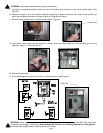
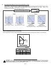
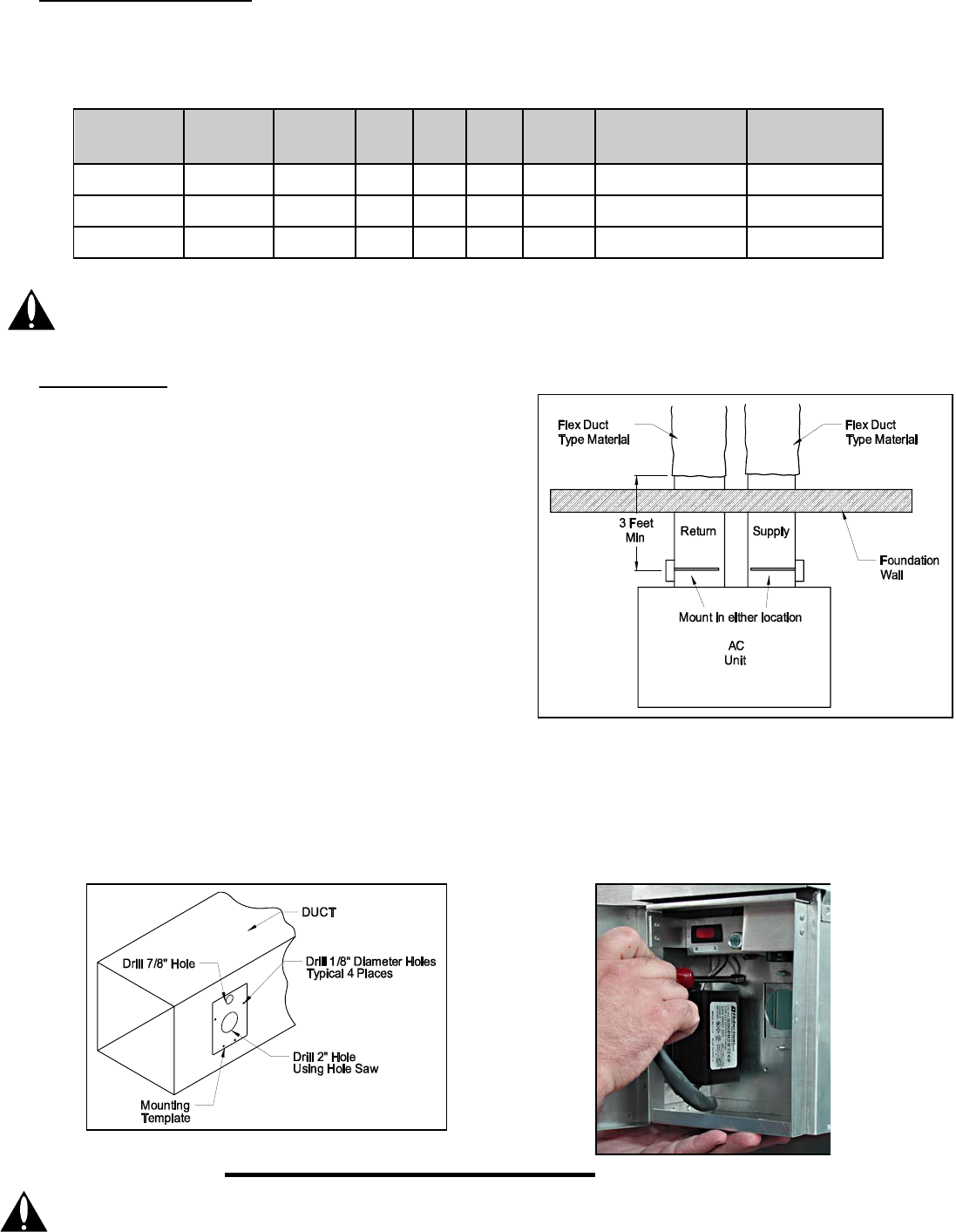
2. Apply mounting template to air duct as shown in Figure 2.
3. Drill 1/8” diameter mounting holes at positions indicated
on template. (See Figure 2)
4. Using a 2” hole saw, drill out lamp hole as shown on
template. (See Figure 2)
5. Drill a 7/8” inspection hole as shown on template. (See
Figure 2)
6. Remove template.
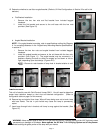
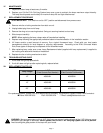
7. Mount unit to duct using the 4 supplied sheet metal
screws. (See Figure 3)
Figure 2
WARNING: Never expose eyes or skin to UVC light from any source. Looking directly at the UVC light may cause
p
ermanent eye damage or blindness. Never operate the UV-Aire™ Air Purifying System out of the plenum.
A
void touching the glass portion of the lamp with your hands.
Figure 3