


9
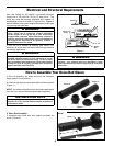
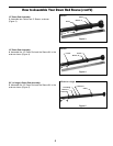
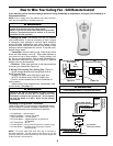
How to Wire Your Ceiling Fan - C20 Remote Control
If you feel that you do not have enough electrical wiring knowledge or experience, have your fan installed by a
licensed electrician.
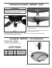
Figure 1bFigure 1a
9V
Battery
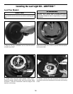
Remote Transmitter
Unit Detail
Receiver Unit Detail
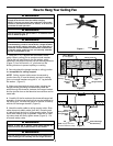
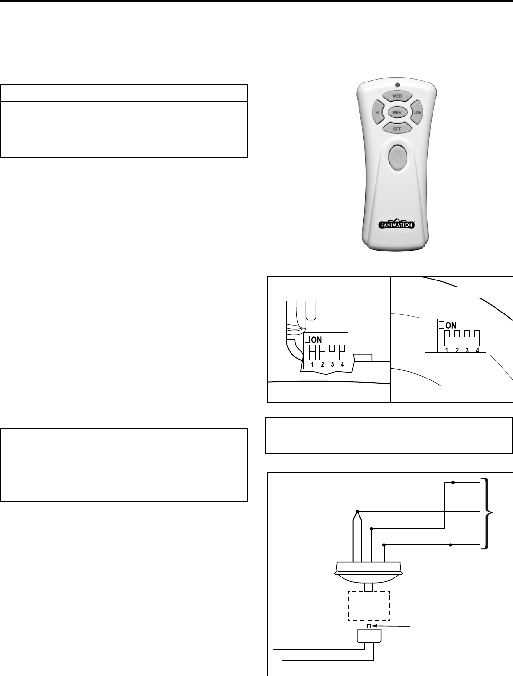
Figure 2
FAN
MOTOR
UNIT
BL-AC IN L
WH-AC IN N
BLUE-FOR LIGHT DOWN
BLK-TO MOTOR L
WH-TO MOTOR N
GRN or BARE GROUND
GRN from hanger ball
GRN from bracket
120 VAC SUPPLY
(User Supplied)
WH-FOR LIGHT DOWN
GRN
Receiver
Unit
Plug from Motor
into Receiver Connector
NOTE: If fan or supply wires are different colors than indicated,
have this unit installed by a qualifi ed electrician.
▲
WARNING
To avoid possible electrical shock, be sure electricity is
turned off at the main fuse box before wiring.
NOTE: If you are not sure if the outlet box is grounded,
contact a licensed electrician for advice, as it must be
grounded for safe operation.
▲
WARNING
Total wattage NOT to exceed 300 watts.
2. Wiring & Connecting Your Ceiling Fan: (Figure 2)
– Green Hanger Bracket and Hanger Ball wires to
BARE (ground) wire.
– BLACK Fan Motor wire to BLACK supply wire.
– WHITE Fan Motor wire to WHITE supply wire.
• Position all connected wires to allow installation of
ceiling canopy.
• Install canopy using threaded rods, lockwashers, and
knurled knobs. (see page 10)
1. Setting the Code: The remote unit has 16 different
code combinations. It may be necessary to test a couple
of frequency code settings to improve signal reception
and/or eliminate interference from other remote control
household items. Multiple fans should have different code
settings to allow independent fan control. To set the code,
perform these steps.
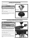
• Transmitter: remove battery cover. Press firmly below
arrow and slide battery cover off. Slide code switches to
your choice of up or down position. Factory setting is all
up. Do not use this position. With a small screwdriver or
ball point pen slide firmly up or down (Figure 1a). Replace
battery cover on the transmitter.
• Receiver: Slide code switches to the same positions
as set on your transmitter (Figure 1b).
Operating & Using Remote Transmitter:
Install 9 volt battery (If not using for long periods of time,
remove battery to prevent damage to transmitter). Store
the transmitter away from excess heat or humidity.
• HI Push Button – high fan speed
• MED Push Button – medium fan speed
• LOW Push Button – low fan speed
• REV Push Button – toggles between air upflow and
air downflow
• OFF Push Button – fan off
• U/L Push Button –
use top portion of light button to operate up light
• D/L Push Button – use bottom portion of light button to operate
optional down light
NOTE: To control either light hold down key to increase or
decrease brightness. Tap key quickly to turn light on or off. The
light keys have auto resume and will stay at the same brightness
as the last time it was turned off.
▲
WARNING
Check to see that all connections are tight, including
ground, and that no bare wire is visible at the wire
connectors, except for the ground wire. Do not operate
fan until the blades is in place. Noise and fan damage
could result.