


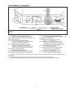
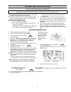
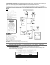
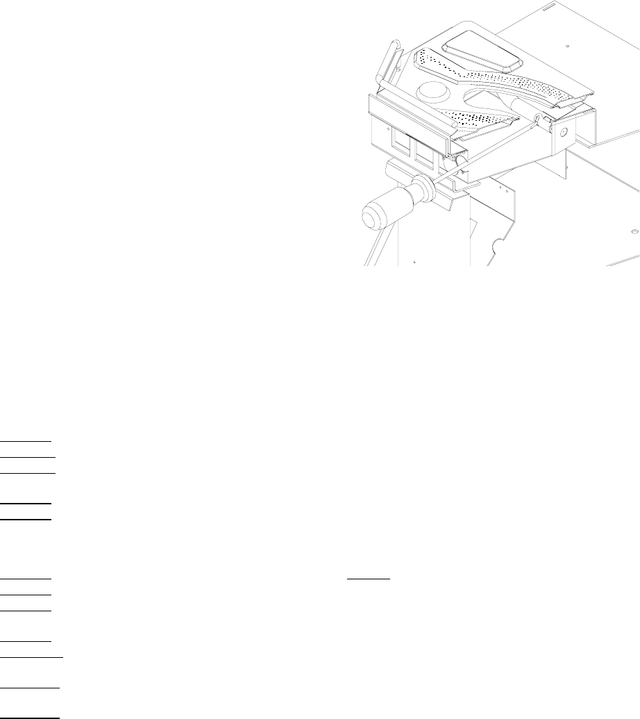
ADJUSTING THE VENTURI
• Remove the ash shelf by undoing the screw at
each end, pull shelf towards you.
• Remove one screw from the cover plate located
below the ash shelf. Loosen the other screw (do
not remove) swing the cover plate out of the way
and tighten screw down to hold it in place.
• With along screwdriver rotate spring clips to open
or close the shutter to the desired setting.
• The burner flame should be a bright
yellow/orange when hot. Excessive blue is to
lean and dark orange with soot is too rich.
FUEL CONVERSION
“Warning” This conversion kit shall be installed
by a qualified service technician in accordance
with the manufacturer’s instructions and all applicable codes and requirements of the authority having
jurisdiction. If the information in these instructions is not followed exactly, a fire, explosion or CO
poisoning may result. The qualified service agency is responsible for the proper installation of this kit.
The installation is not proper or complete until the operation of the converted appliance is checked as
specified in the owner’s conversion kit.
Please read and follow these instructions. Also please read the instruction guide lines provided by S.I.T on how to
remove and install the HI-LOW regulator.
STEP 1.
Carefully inspect all parts supplied with this conversion kit.
STEP 2. Shut the gas off and disconnect the main gas line from the unit.
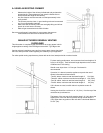
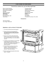
STEP 3. Open the door by unscrewing the ½” bolt on the right hand side of the stove. Lift door off the hinges mounted on
the left-hand side. Remove the burner tray top for the appliance
STEP 4. Change the regulator on the front of the gas valve. (Follow the instructions provided by S.I.T)
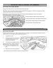
STEP 5. To change the pilot orifice: First, remove the two (2) T-20 Torx screws that hold the pilot assembly to the burner
tray. Lift the pilot assembly from the burner tray. Using a 10mm wrench, disconnect the pilot line from the pilot
assembly and remove the pilot injector. Install the new pilot injector.
(BE CAREFUL WHEN TIGHTENING THE PILOT FITTING, YOU COULD BREAK THE CERAMIC IGNITER ELECTRODE).
STEP 6. Re-install the pilot assembly in the reverse order of STEP 5.
STEP 7. Remove the burner orifice with a ½” deep socket.
STEP 8. Install the new orifice supplied making sure that the orifice is in the correct location. Be sure to put a bead of pipe
thread sealant or approved Teflon tape on the orifice before installing into the burner assembly.
STEP 9. Reinstall the burner tray, log set and door.
STEP 10. Re connect the gas line to the unit. Do a leak check using a soap and water solution or an approved manner on
the gas supply line and the pilot tubing.
STEP 11. Re-light the appliance to insure proper operation and proper flame appearance. Be sure to adjust the venturi setting
to achieve an efficient flame in the fireplace.
STEP 12. MAKE SURE that the sticker provided by S.I.T is installed to signify that this valve has been converted to a different
type of fuel. Also make sure that the rating plate has a conversion label to show that this unit has been converted to
a different fuel type.
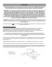
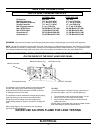
A VISUAL CHECK OF THE REGULATOR KNOB IS NECESSARY TO DETERMINE WHETHER OR NOT THE
REGULATOR IS THE CORRECT PART. A 50% TURN DOWN REGULATOR WILL HAVE ONLY ONE
CORNER ON THE KNOB.
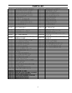
1 50% turn down HI-LOW Regulator w 3 T-20 Torx
screws
1 T-20 tamper proof Torx screwdriver bit
1 pilot injector
1 Main orifice
1 Pilot assembly mounting gasket
NATURAL GAS PROPANE
Pilot Orifice. .51mm .35mm
Burner Orifice. #42 dms #53dms
Venturi Settings 1/16” min ¼” min
15