


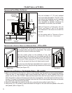

Non-combustible
floor protection.
Existing floor
(combustible)
6"
(15 cm)
3" (7.5 cm)
Pedestal
Wall
thimble
Fresh air
intake
Rodent
mesh cap
45°
elbow
12"
(30.5 cm)
Surround Panel
Combustible
materials and
structure
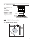
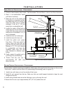
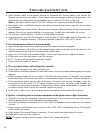
Installation
INSTALLATION FOR A BUILT-IN HEATER:
This unit includes a 3” (75 mm) pedestal
and surrounding faceplates. The part of the
unit behind the faceplate can be enclosed
with combustible material. It has 1” (25
mm) standoffs to establish clearances to
combustibles to the back, top and sides.
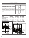
Refer to “CLEARANCES TO COMBUSTIBLES - BUILT-IN
HEATER“ and Figure 11 and 12 for the size
and placement of the alcove to be built for
the unit.
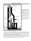
For the venting refer to “HORIZONTAL EXHAUST
THROUGH WALL INSTALLATION - FREESTANDING“.
Figure 31: Built-in heater installation.
24
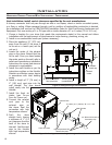
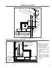
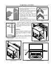
INSTALLATION OF CONTROL PANEL INTO SURROUND PANEL - FPI AND BIH:
Figure 32: Control
Panel Cover.
Figure 33: Control
Panel Back.
When installing the control panel into the surround panel,
the surround does not need to be assembled. The control
board will be found in behind the firebox.
Place the control panel on the backside of the right
surround panel so the hinge is on the outside and the top
and bottom holes on the control panel line up with those on
the surround. Attach using two (2) T-20 screws through the
front of the surround into the circuit board control panel.
After the surround has been assembled and is ready to be
installed on the unit, plug the wiring harness into the control
panel (see Figure 33).
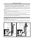
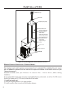
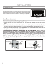
INSTALLATION AND REMOVAL OF THE SURROUND PANELS - FPI AND BIH:
1. Attach one side trim to the top trim, using a corner bracket (see Figure 34) to secure pieces together.
There are two (2) main pieces to each corner bracket (see Figure 35). When installing the corner
pieces into the trim, the “B FACE” sides must face each other and the screw heads are to face out.
With the bracket in place and the top and a side trim snug together, use a flat head screwdriver to turn
the two (2) screws in the bracket to tighten it into the trim. Do not over-tighten the corners or the side
trim cannot be removed during servicing.
2. Attach the other side trim piece to the top trim, using the same method used in Step 1.
3. Using three (3) T-20 screws on each side attach the hinges on the side surround panels to the unit’s
side panels (refer to Figure 37).