


V
e
n
t
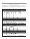
R
e
s
t
r
i
c
t
o
r
P
o
s
i
t
i
o
n
20’
(6.10m)
25’
(7.62m)
30’
(9.14m)
32’
(9.75m)
41
3
/
4
”
(106cm) from
floor
0’
(0m)
0’
(0m)
15’
(4.57m)
15’
(4.57m)
17’
(5.18m)
5’
(1.52m)
5’
(1.52m)
10’
(3.05m)
10’
(3.05m)
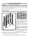
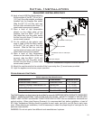
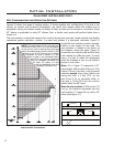
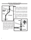
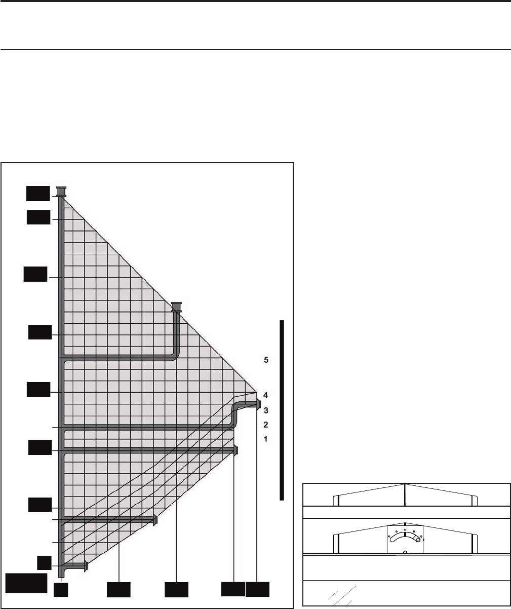
Figure 31. Possible Vent Congurations for Top Vented; Vertical
and Horizontal Terminations.
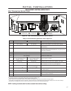
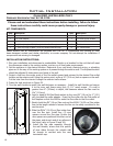
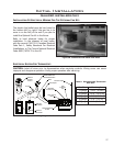
Figure 32. Possible Vent Restrictor Positions.
Initial Installation
QUALIFIED INSTALLERS ONLY
VENT CONFIGURATIONS AND RESTRICTOR SETTINGS:
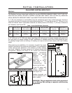
Figures 31 shows the range of venting options, it shows possible vent congurations if the unit is top
vented, for vertical and horizontal terminations, any layout that remains within the shaded area is
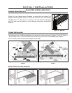
acceptable. Having the fewest number of elbows is ideal, as they tend to disrupt air movement. Using
45˚ elbows is preferable to using 90˚ elbows. Also, a shorter vent system will perform better than a
longer one.
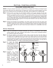
The vent restrictor controls the amount of air moving through the vent pipe. Longer vertical vent lengths
necessitate greater restriction; position 1 is open and position 5 is maximum restriction. Figure 31
NOTE: The total length of the vent pipes can
not exceed 32 feet (15.12 m). Any combination
of rise and run can be used as long as it lays
within the shaded area (a total of three (3) 90°
elbows or six (6) 45° elbows can be used).
In addition to what is shown, if a 90°
elbow is used in the horizontal plane,
3 feet (91.4 cm) must be subtracted
from the allowable horizontal run
(for each 45° elbow, 1 feet
must be subtracted from the
allowable horizontal run).
shows the vent restrictor position required,
relative to the length of vent pipe. The
vent restrictor is located in the center of
the replace, above the glass. Figure 32
shows the vent restrictor dial and the holes
that indicate the different levels. To avoid
injury, it is best to make this adjustment
when the replace is cool or use welder’s
gloves or oven mitts.
Note: 0,0 in Figure 31 represents a 90˚
bend directly off the outlet of the unit, 41
inches (106 cm) from oor, in all horizontal
instances except when using Selkirk and
having less than a 4 feet (1.22 m) rise
and 8 feet (2.44 m) horizontal offset. In
this case, a 1 foot (30.5 cm) rise must be
added below the 90˚ bend.
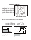
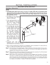
Note for rear vented: At 29 inches (75
cm) up, the maximum horizontal rear exit
vent length is 17 inches (43 cm) with a 45°
elbow (see Figure 17).
22