


30
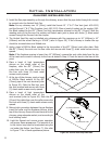
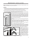
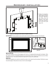
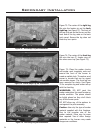
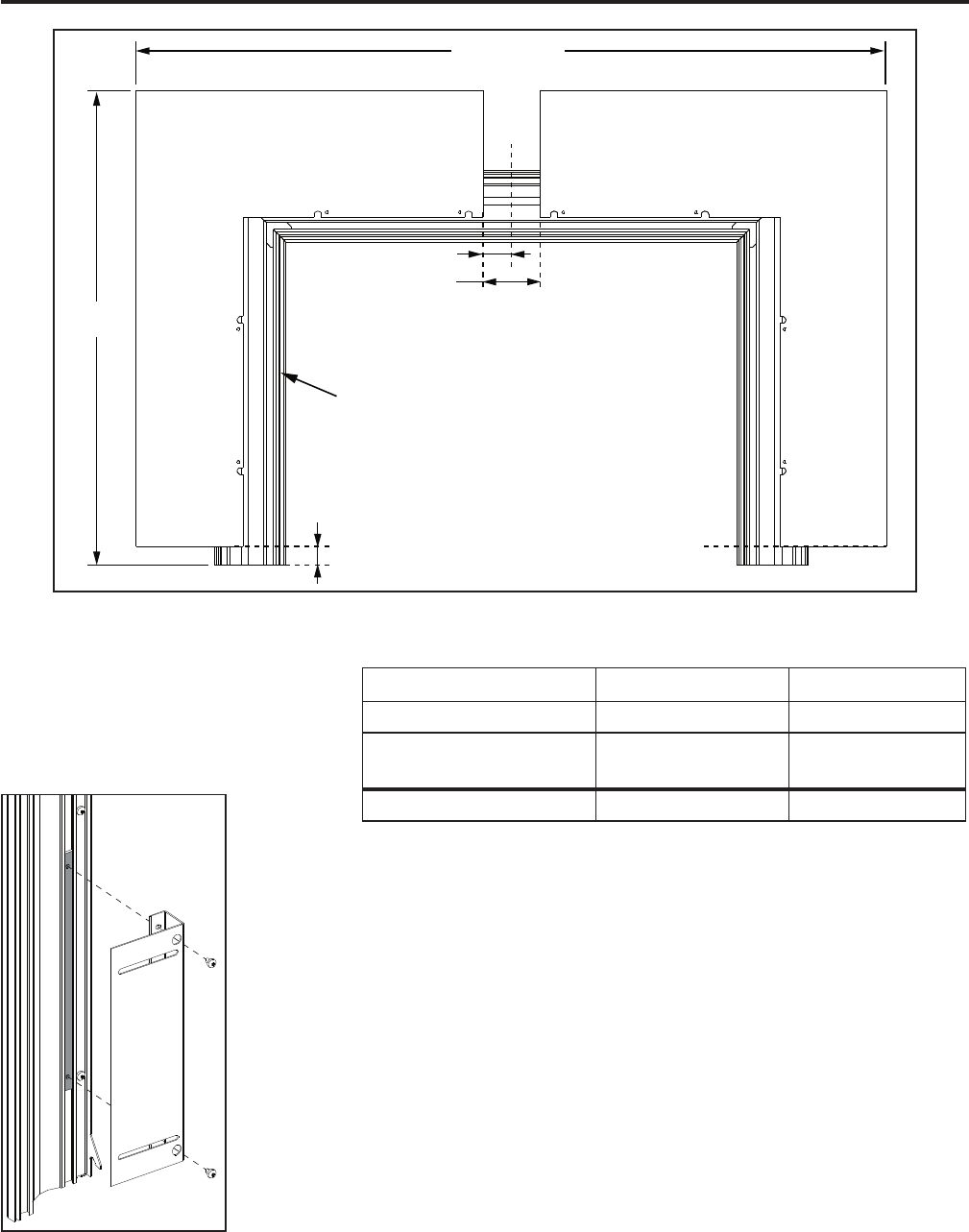
Figure 62: Installing
Mounting Bracket.
Table 7 example, the differences are 1” (25mm) and 3” (76mm).
c) Mark the height difference on the left and right trim sides. Using the
example, they would be marked 1” (25mm) from the bottom of each side,
see dimension “A” in Figure 61.
d) Mark the center of the top trim, 15” (397mm) from either side. From the
center line mark half the width distance on either side. Using the example of
3” (76mm), there would be marks 1” (38mm) on either side of the center
line, see dimension “B/2” in Figure 61.
9. Fasten a mounting bracket to each of the four (4) mounting bracket backs
using two (2) #8 T-20 screws (see Figure 62). They should be tight enough
that they hold together but loose enough to slide them in the slots.
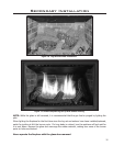
10. Line the ends of the surround corners with the marks from step 8. Move the
mounting brackets until the holes on the surround line up with the slots on
the mounting brackets. When everything is lined up, secure the surround to
the mounting brackets with eight (8) #8 T-20 screws (see Figure 63). Also
tighten the eight (8) screws from step 9.
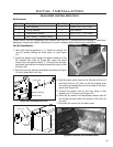
B
B/2
A
Note: Mounting brackets
removed for clarity
Adjustable
Surround Corner
Adjustable
Surround Corner
Trim (Classic or Colonial)
Required Width
Required
Height
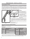
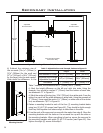
Table 7: Adjustable Surround Example, Relates to Figure 61.
Height Width
Area Needed to Cover 25
1
/16” (637mm) 39” (997mm)
Minimum size of Large
Adjustable Surround
24
1
/16” (612mm) 36” (921mm)
Difference 1” (25mm) = A 3” (76mm) = B
Figure 61: Marking offsets on Trim, Relates to Table 7.
b) Subtract the minimum size of
the surround (23
13
/16” (555mm) x
31” (809mm) for the small and
24
1
/16” (612mm) x 36” (921mm)
for the large) from the size needed.
Write down the difference. In the
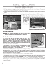
Secondary Installation