


17
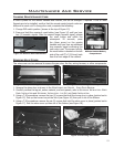
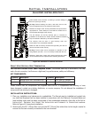
Initial Installation
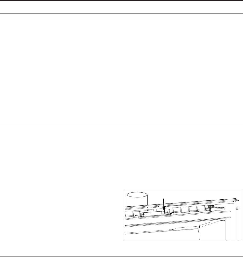
Door removed for clarity
” Tube
B-VENT MODEL:
WARNING: This appliance has been designed to operate by drawing combustion air and dilution air
from the room. It is also designed to draw room air for proper heat circulation from the sides of the unit.
Blocking or modifying these openings in any way can create hazardous situations, either through poor
venting or by overheating. It is important that this unit has sufcient air circulation for proper venting
and combustion. Provisions must be made for the supply of adequate combustion and ventilation air.
These openings must not be blocked. The appliance must not be connected to a chimney ue servicing
a separate solid fuel-burning appliance.
A vent connector of Type B vent material must be installed with a minimum clearance of 1” (25mm)
to combustible material, including passage through either a combustible wall or partition and must be
securely assembled in accordance with the manufacturer’s certied instructions.
A vent connector must be install with neither dips nor sags and must be securely supported by non-
combustible hangers suitable for the weight and design of the materials employed. A slip joint in the
horizontal section of a vent connector must be secured with either sheet metal screws, or other approved
means to prevent sagging.
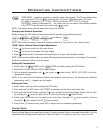
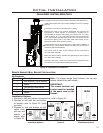
AUTOMATIC FLUE GAS SPILL SWITCH - B-VENT MODEL ONLY:
NOTE: This heater must be properly connected to a venting system. This heater is equipped
with a vent safety shutoff system designed to protect against improper venting of combustion
products. This safety switch is located on the rear of the appliance. If the switch trips more
than once, the venting should be inspected by a qualied service technician for possible
blockage or severe down draft conditions.
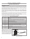
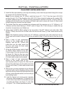
The draft hood must be in the same pressure zone as the air inlet. Inspect for draft from the front of
the unit at the ” tube (shown in Figure 28). Note that when the door is installed the tube is not visible
when looking straight at the unit. Check for a draft using smoke; a vacuum or suction into the tube will
indicate proper drafting. If air is blowing out of the tube the problem must be corrected before the unit
can be started.
This model can be vented with 3” aluminum or
stainless steel ex vent and/or certied Type B Gas
Vent. The ue collar of the appliance will t inside
of a standard 3” vent and may be fastened directly
to the vent. Check periodically that the vent is
unrestricted and an adequate draft is present when
the unit is in operation.
Figure 28: Draft check.
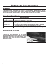
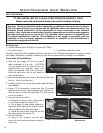
PREPARING YOUR SONNET FOR INSTALLATION:
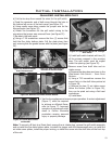
• Remove the packaging from the appliance and surround panels; check to make sure there is no
damage. Carefully check the glass door. Do not use the unit if it is damaged. In the event damage is
found, please report it to both the courier and your dealer as soon as possible.
• Carefully clean the replace and ue before installing the stove. Failure to do so may result in fumes
or dirt being blown into the room and may cause a re leading to death or serious injury.
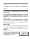
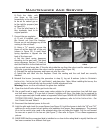
• If one or more Sonnets are to be installed, conrm that the remote control signal codes are different
for each unit, refer to MAINTENANCE AND SERVICE - CHANGING REMOTE HANDSET CODE.
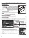
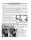
1. Remove the unit from the box and remove all packaging material from the appliance.
2. Remove door. See MAINTENANCE AND SERVICE - GLASS DOOR REMOVAL.