


15
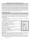
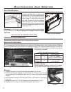
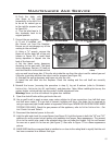
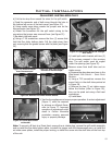
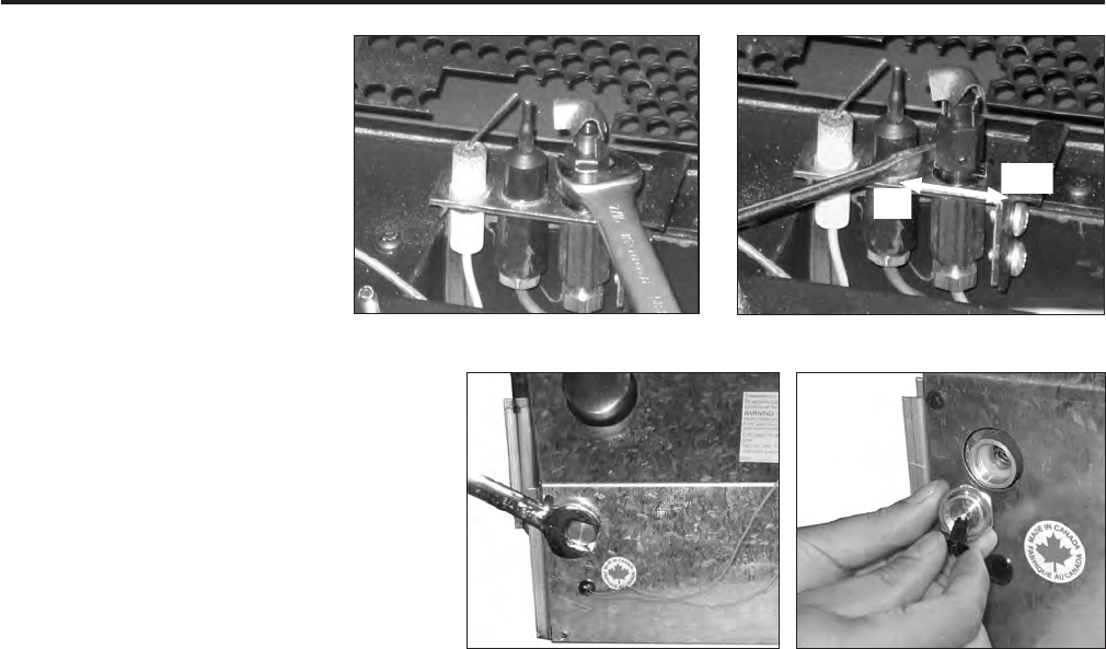
Figure 23: Turn Pilot Head.
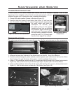
the Sonnet out from the replace.
Ensure you do not damage any of the
venting or the unit itself.
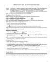
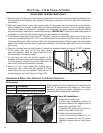
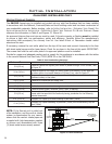
b) Using a
7
/8” wrench, remove the
brass nut at the back left of the unit
(shown in Figure 25). A small black
spring depressor is clipped into the
back of the brass nut.
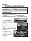
c) Set the black spring depressor
according to the gas used. The black
spring depressor has two (2) teeth at
each end that t in to the brass nut but
Figure 24: Settig Regulator gas type
to LP.
only one end has a larger disc. If the disc sits inside the cap then the valve is set for natural gas and
if the disc is pointing out then the valve is set for propane (see Figure 26).
d) Reinstall the spring depressor and brass nut onto the unit.
e) Install the unit back into the replace. Check the venting and the unit itself are correctly
installed.
8. Reinstall the burner (reversing the procedure in step 4), log set & embers (refer to SECONDARY
INSTALLATION - INSTALLING LOG SET AND EMBERS), and glass door. Note: When installing the burner, the
venturi shutter rod should slip into the venturi shutter adjustment hole.
Warning: Never run the unit without the glass door installed.
9. Open the shut-off valve at the gas line to the unit.
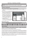
10. Use a small brush to apply a warm soapy water solution to all gas connections (use half dish soap
and half warm water). If a gas leak is present, bubbling will occur. Gas leaks can be repaired by
using an approved pipe thread sealant or approved Teon tape. NEVER USE AN OPEN FLAME WHEN
TESTING FOR LEAKS. Check the gas pressure of the appliance, refer to INITIAL INSTALLATION - GAS
LINE CONNECTION and Table 6.
11. Reconnect the electrical power to the unit.
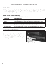
12. Light the pilot and check for proper ames (see Figure 8). Light the burner in both the “HI” and “LO”
positions to verify proper burner ignition and operation and proper ame appearance. The amount
of air to the venturi may need to be adjusted using the rod under the rebox. Pull the rod forward
for more air or push it in for less air (see Figure 7). Also refer to Figure 77 for a ame appearance
picture.
13. MAKE SURE that the conversion label is installed on or close to the rating label to signify that the unit
has been converted to a different fuel type.
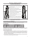
LPG
NG
Figure 26: Set Gas Type for
Valve.
Figure 25: Remove Brass Cap.
b) Push the slider, with
your nger or at head
screwdriver, to the left if it is
to be set for natural gas or
to the right for propane (see
to Figure 24).
c) Turn the pilot head a
turn clockwise; back to its
original position.
7. Convert the gas regulator:
a) If unit is installed, pull
Maintenance And Service