


26670-0-0110 Page 27
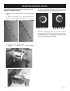
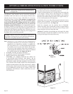
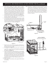
4. Insert blower assembly into interior, bottom of rebox.
Note: On peninsula models, the blower must be installed at
the end which has the brick panel installed. Position blower
assembly so that you align the notch on back of blower as-
sembly with the center screw on side/end panel, then push
the blower assembly against rebox outer panel. The blower
wheel must be centered with the side/end wall of the rebox.
The magnets on the back and bottom of blower assembly will
sufciently hold blower assembly in place. See Figure 23.
5. Once the blower assembly is in position, locate the plug but-
ton in the top corner of the rebox. Remove the plug with a
standard screwdriver and discard plug.
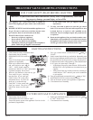
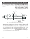
6. Next, nd the fan control switch and wire assembly. Feed the
wires through the hole at the top of the rebox, and secure the
fan control switch with two (2) #6 screws (provided). The fan
control wires will slide down between the rebox and outer
wrap near the blower assembly. See Figure 22.
7. Route the wires away from moving parts of the blower as-
sembly and retain wires together near the blower motor using
the plastic purse clip provided.
8. To complete the installation, plug the power cord into the
junction box receptacle previously installed in the bottom of
the replace. See Figure 23.
9. Once all connections are made electrically, it is recommend-
ed that you test the blower fan control operation by turning
on power to the blower (Caution: 110 Volt). Turn the replace
on and let run until blower is activated. This should take ap-
proximately 10 to 20 minutes from a cold start. Once blower
is activated, check for proper operation. Do not place hands
near blower assembly or other wiring while power is on.
10. Replace louver(s).
11. This completes the installation of the optional FBB5 Blower
kit accessory.
Note: This blower is equipped with a heat activated fan control
switch. Blower will operate when the replace warms up,
and will turn off automatically when the replace cools
down. The time will vary for the activation of the fan con-
trol switch depending on several factors including replace
type, BTU input variables, and log set style. Generally, it
may take from 10 to 20 minutes to activate blower/fan con-
trol from a cold start.
Figure 22
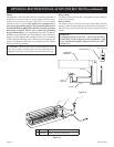
Figure 24
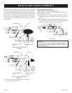
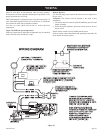
USE OF ASTANDARD
ON/OFF WALL SWITCH TO
OPERATE OPTIONAL BLOWER
Figure 23
JUNCTION
BOX
POWER CORD
BLOWER ASSEMBLY
(CENTER AND INSTALL
AGAINST OUTER WRAP
AS SHOWN)
OUTER
WRAP
FAN
CONTROL
SWITCH
WIRE ASSEMBLY
FROMFAN
CONTROLSWITCH